Pneumatic tire including sipes

a technology of pneumatic tires and sipes, applied in the field of pneumatic tires, can solve the problems of deterioration of external appearance and noise, steps due, and tend to occur

Inactive Publication Date: 2001-09-04
BRIDGESTONE CORP
View PDF18 Cites 15 Cited by
  • Summary
  • Abstract
  • Description
  • Claims
  • Application Information

AI Technical Summary

Problems solved by technology

Generally, in pneumatic tires provided with block patterns, irregular wear known as heel-and-toe wear, results in steps due to wear at the leading (step-in) edges and the trailing (kick-out) edges of blocks, and tends to occur.
Such wear is accompanied by a deterioration in external appearance and noise, and there is a definite need to solve this drawback.
However, it is difficult to greatly change the angle of the groove wall surfaces due to problems such as removing the tire from a mold at the time of vulcanization or the like.
Further, as wear progresses, the width of the groove has a distribution which differs greatly than that at the time the tire was new, which is not preferable from the standpoint of performance nor from the standpoint of external appearance
However, this structure can only be applied to patterns having a specific orientation, and is not practical.
Generally, blocks at the shoulder sides of a pneumatic tire are displaced toward the center at the time of step-in, and thereafter, contact the road surface, and at the time of kick-out, return while sliding toward the outer sides, such that wear is generated at these times.
In a block pattern, due to the shearing strain between a leading edge (heel side) which is a preceding trailing edge region and a trailing edge (toe side) which is a following trailing edge region, the amount of wear of the trailing edge (the following trailing edge region) is greater than the amount of wear of the leading edge (the preceding trailing edge region), and thus heel-and-toe wear is generated.
Further, it is known that when heel-and-toe wear is generated at shoulder side blocks, the noise generated at the time the blocks contact the ground becomes large.
As heel-and-toe wear is generated, the force received from the road surface increases at the leading edges of the blocks at the shoulder portions.
This effect increases the ground-contact pressure of the leading edge of the block of the next pitch, and the striking noise at the time of stepping into the block increases.

Method used


Image

  • Pneumatic tire including sipes
  • Pneumatic tire including sipes
  • Pneumatic tire including sipes

Examples


example tire 1

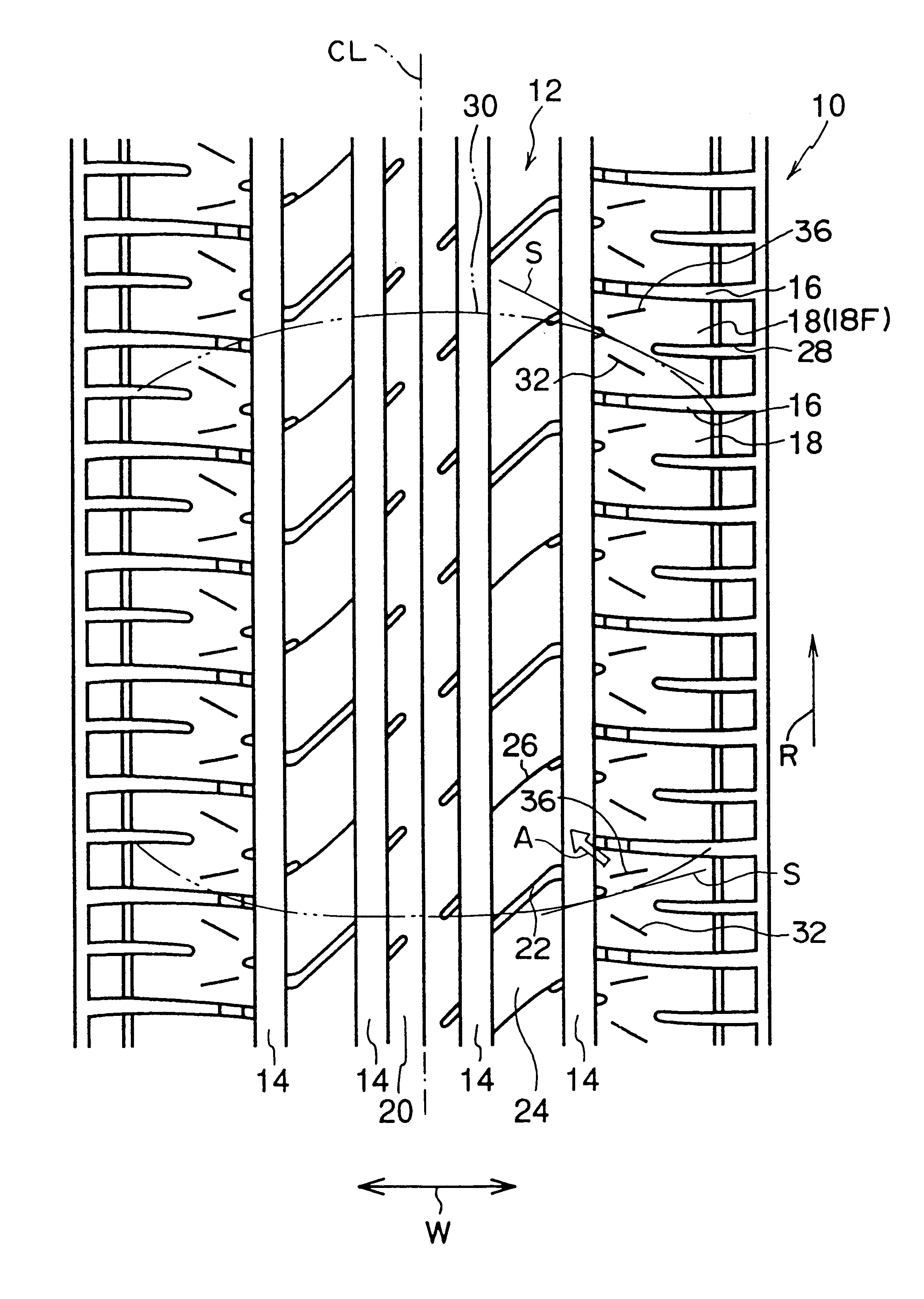
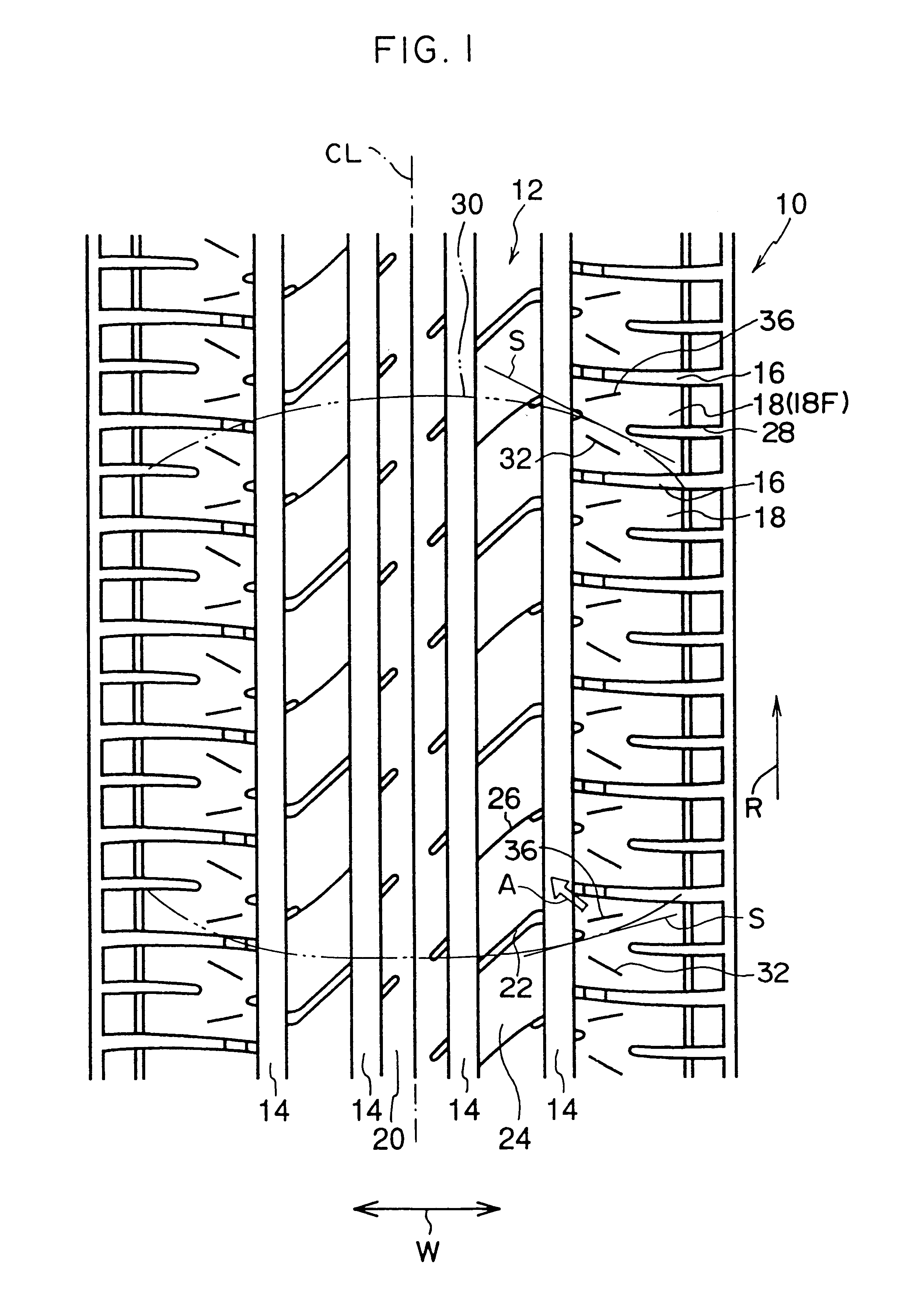
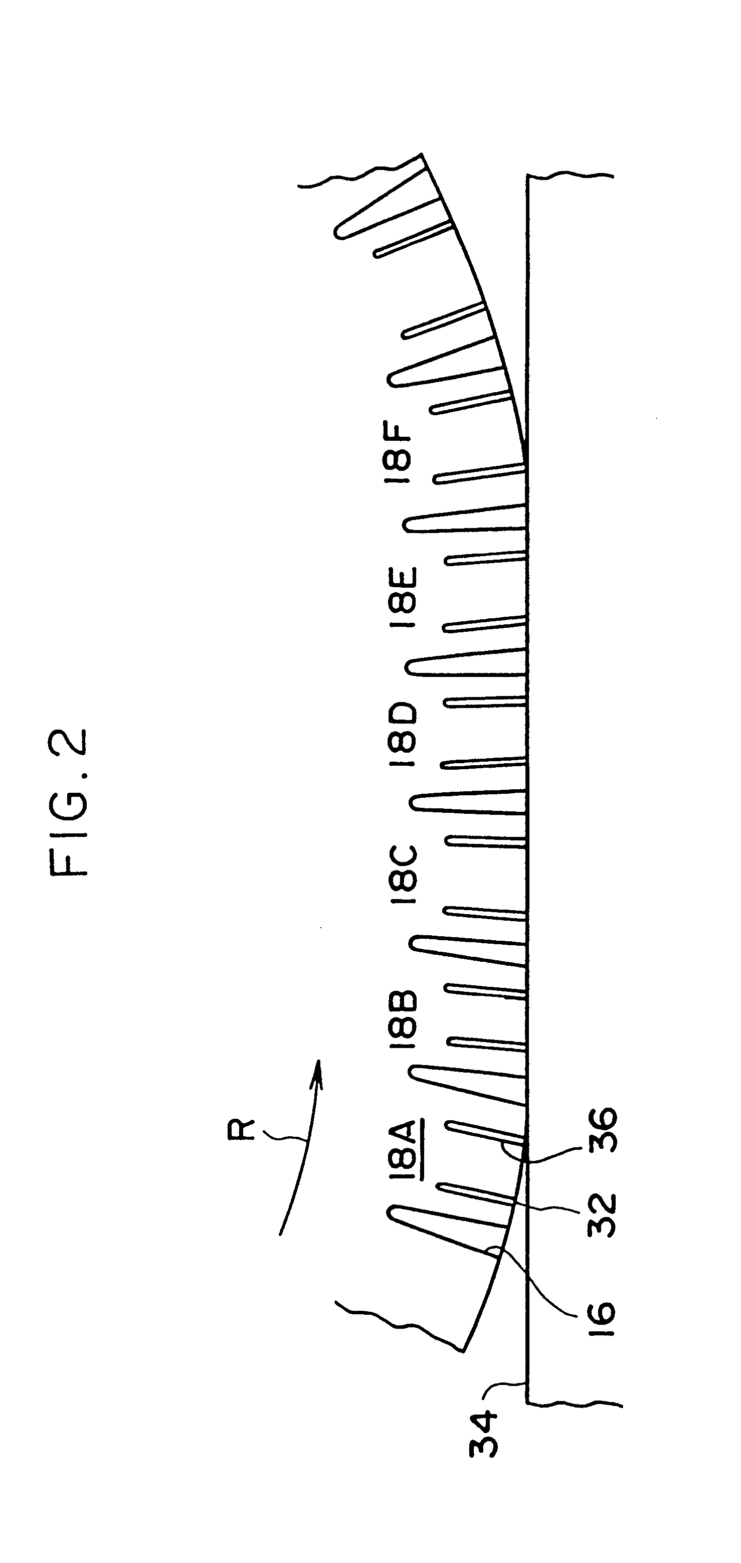
The tire of the first embodiment (see FIG. 1).

Conventional Example Tire 1:

The same pattern as that of Example Tire 1, but sipes were not formed in any of the blocks.

example tire 2

As shown in FIG. 7, the pattern was the same as that of Example Tire 3, but only the sipes 48 at the trailing edge regions were formed in the shoulder blocks 42.

example tire 3

The tire of the second embodiment (see FIG. 5).

Conventional Example Tire 2:

As shown in FIG. 8, the pattern was the same as that of Example Tires 2, 3, but no sipes were formed in the blocks.

(Experimental Method)

The wear test was carried out by a flat belt wear testing machine at which the experimental tire was mounted to a 7.5 J rim and filled to an internal pressure of 2.0 kgf / cm.sup.2. The experimental conditions were as follows.

road surface: Safety Walk type B (trade name, manufactured by 3M Co., Ltd.)

slip angle: 0.5 degrees

load braking force: 45 kgf

running distance: 300 km

room temperature: 30.degree. C.

load: 450 kgf

speed: 50 km / h

In the evaluation of the comparison, of the fires the difference in the amount of wear between the trailing edge and the leading edge of the block at the shoulder side was expressed as an index with the Conventional Example Tire being 100. Higher values indicate smaller wear differences which is better. The results are shown in following Tables 1 and 2.

T...


PUM


Abstract

A pneumatic tire in which a sipe, which is substantially parallel to a contour line of a trailing edge of a ground-contact configuration, is formed in a trailing edge region of each block at shoulder sides of the pneumatic tire. From a time of step-in to a time of kick-out of a block, the effect of shearing strain which is transmitted to a trailing edge from a preceding trailing edge portion is mitigated, and movement of the trailing edge of the block with respect to a road surface is suppressed. Accordingly, wear at the trailing edge of the block, i.e., heel-and-toe wear, is suppressed, and noise caused by heel-and-toe wear is reduced.

Description

1. Field of the InventionThe present invention relates to a pneumatic tire having at the tread thereof blocks in which sipes are formed, and in particular, to a pneumatic tire in which irregular wear is suppressed and noise at the time of wear is decreased.2. Description of the Related ArtGenerally, in pneumatic tires provided with block patterns, irregular wear known as heel-and-toe wear, results in steps due to wear at the leading (step-in) edges and the trailing (kick-out) edges of blocks, and tends to occur. Such wear is accompanied by a deterioration in external appearance and noise, and there is a definite need to solve this drawback.With heel-and-toe wear a step is formed due to earlier wear at the toe side which is the trailing edge, than at the heel side which is the leading edge.An example of a method for improving heel-and-toe wear is a method in which the angle of the groove wall surfaces with respect to a normal line which is orthogonal to the direction in which the gro...

Claims


Application Information

Patent Timeline
Patent Type & Authority Patents(United States)
IPC IPC(8): B60C11/00B60C11/12B60C11/01B60C11/11B60C11/04B60C11/13
CPCB60C11/00B60C11/01B60C11/0332B60C11/12B60C11/11Y10S152/904B60C2011/1254Y10S152/03
Inventor TOMITA, ARATA
Owner BRIDGESTONE CORP
Why Eureka
Try Eureka