Sequential aerobic/anaerobic solid waste landfill operation

a landfill operation and aerobic/anaerobic technology, applied in the field of aerobic/anaerobic solid waste landfill operation, can solve the problem that the vertical injection is most likely not as efficient as the horizontal pipe/trench application

Inactive Publication Date: 2001-09-04
WM INTPROP HLDG L L C
View PDF10 Cites 73 Cited by
  • Summary
  • Abstract
  • Description
  • Claims
  • Application Information

AI Technical Summary

Benefits of technology

It is another object of this invention to provide a method for degrading solid waste that accelerates landfill aerobic and / or anaerobic degradation.
It is still another object of this invention to provide a method for degrading solid waste that improves degradation by-product quality.
In yet another embodiment, this invention is a method for reducing noxious landfill gas emissions.

Problems solved by technology

However, the state of the first energy crisis started in 1973 led to projects focused on enhanced methane production.
Some problems were noted with gas leaks and water infiltration.
The upper quarter section of the landfill was the least degraded, showing that vertical injection most likely is not as efficient as horizontal pipe / trench applications.

Method used


Image

  • Sequential aerobic/anaerobic solid waste landfill operation
  • Sequential aerobic/anaerobic solid waste landfill operation
  • Sequential aerobic/anaerobic solid waste landfill operation

Examples


Embodiment Construction

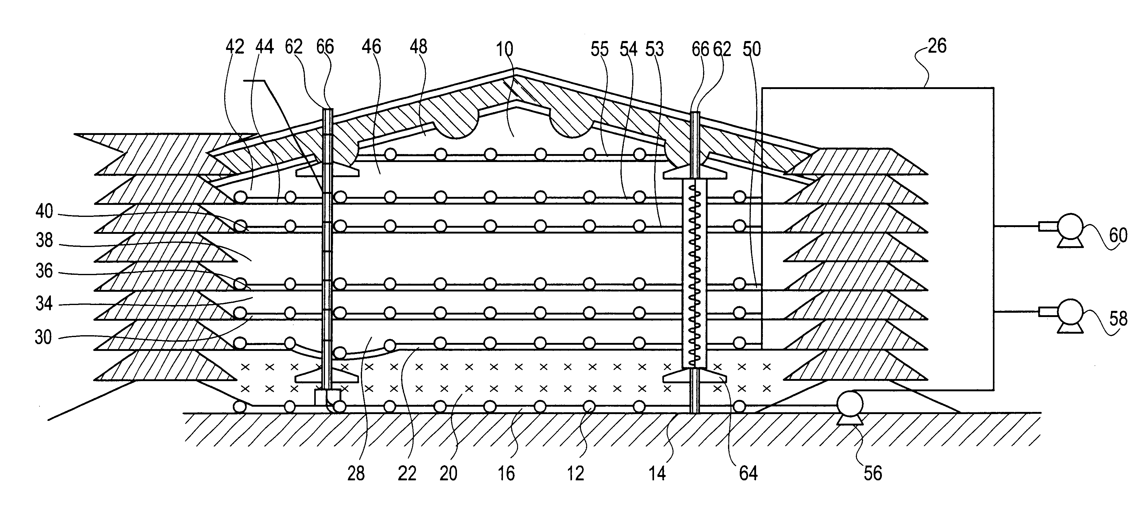
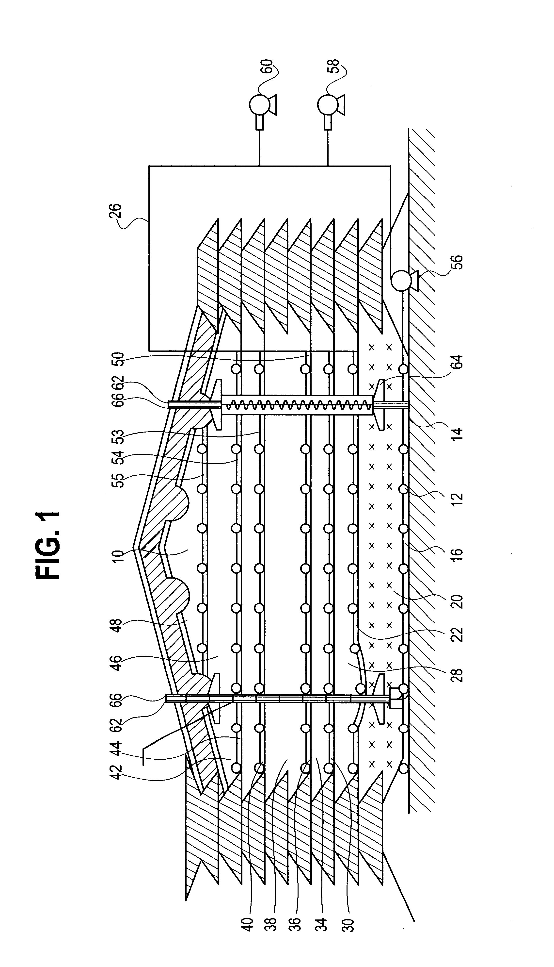
The present invention relates to a landfill bioreactor and to a method for constructing the bioreactor that allows for the sequential aerobic and / or anaerobic bioremediation of biodegradable waste lifts.

FIG. 1 is a side cross-section view of a completed landfill bioreactor 10 of this invention. Landfill bioreactor 10 includes a leachate withdraw system 12 located at bottom 14 of landfill bioreactor 10. Landfill bioreactor 10 may include a bottom liner 16. If used, bottom liner 16 should be essentially impervious to liquids. Alternatively or in addition to having a bottom liner 16, the bottom of the landfill may include a layer of clay, cement or some other seal material. Generally, leachate withdraw system 12 will be located in a layer of gravel or some other pervious material. Locating the leachate withdrawal system 12 in gravel or some other porous material allows for the collection of leachate around the withdraw system 12. In addition, leachate withdraw system 12 will typically ...


PUM


Abstract

Landfills including multiple lifts having horizontal piping layers and methods for their use to accelerate anaerobic and / or aerobic degradation of municipal solid waste to increase landfill capacity.

Description

(1) Field of the InventionThis invention concerns landfill bioreactors and methods for their use to accelerate anaerobic and / or aerobic degradation of municipal solid waste in a manner that increases the landfill capacity.(2) Description of the ArtThe bioreactor landfill concept has been examined in lab and pilot scale projects since the 1960's (Merz). Merz found that placing refuse in thick lifts with continuous leachate spraying on the working face can provide increased landfill densities of 35%. He also discovered that a landfill constructed in an aerobic manner with leachate / water addition can increase settlement rates as much as three times that of an anaerobic landfill. In 1969 the U.S. Public Health Service (predecessor to USEPA), funded research to investigate processes that would result in maximum conversion of municipal solid waste (MSW) to gas (methane and CO2). Since energy was cheap at the time, a goal was to reduce the weight and volume (i.e., increase the density) of ...

Claims


Application Information

Patent Timeline
Patent Type & Authority Patents(United States)
IPC IPC(8): B09B1/00
CPCB09B1/00
Inventor HATER, GARY R.GREEN, ROGERHAMBLIN, GERARD
Owner WM INTPROP HLDG L L C
Why Eureka
Try Eureka