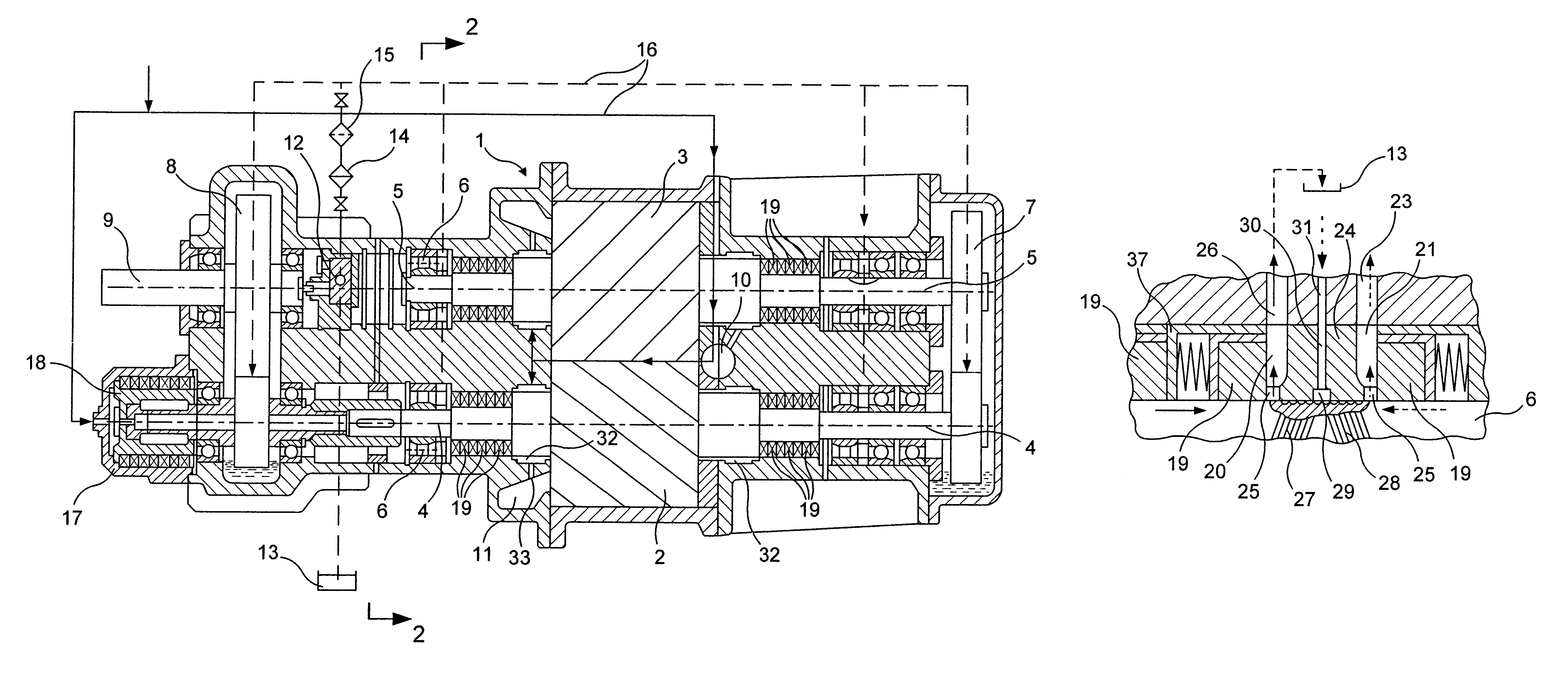
On shafts 4 and 5 of the screws 2 and 3 between bearings 6 and said screws, i.e. in zones of the most probable contact of steam and oil, separators of steam and oil are located. Each separator of steam and oil includes a plurity of seal rings 19, adjacent to one another for preventing penetration of steam or oil from the opposite directions. Between the adjacent seal rings 19, the means for discharging the steam and / or oil are located.
The means of discharging the steam and / or oil is made in the form of, at least, two spaces 20 and 21 (FIGS. 3,4), each of which is located between the seal rings 19, and the first space 20, located on the side of a bearing, is connected by a channel 22 with the
atmosphere--to serve as a drainage space, and the second space 21, located on the side of the associated screw, is connected by means of a channel 23 with the outlet
branch pipe. To increase the efficiency of isolation of the
high pressure chamber from oil a means of forced
discharge of steam and oil may be provided.
On a surface of the shafts 4 and 5 (FIG. 4) at
a site of their interaction with diaphragm 24 opposite directed
helical grooves 27 and 28 are made, inputs of which are connected by means of ring recess 29 and channel 30 made in diaphragm 24 with the
atmosphere, and outputs--with an appropriate clearance 25, thus the groove 27, connected with clearance 25, connected with a hydraulic reservoir 13, is made with a direction appropriate to a direction of the drive screw 2 for support of a forced discharge of oil to a hydraulic reservoir 13 through clearance 25 by pressure of the air, providing, thus, the reliable isolation of the oil and steam environments promoting the increase of the efficiency and
life expectancy of the
machine as a whole. It is feasible to form the
helical grooves 27 and 28 in diaphragm 24 at the site of its interaction with the shaft of the screw. The channel 30 is connected with the
atmosphere by means of the channel 31.
The steam under high pressure comes in inlet
branch pipe 10 and produces in rotation of screws 2 and 3 (FIG. 1,3 and 4). Depleted steam comes out through the outlet
branch pipe 11 under pressure exceeding atmospheric. At the same time the steam from its source under high pressure comes into the cylinder 17, where acting on the
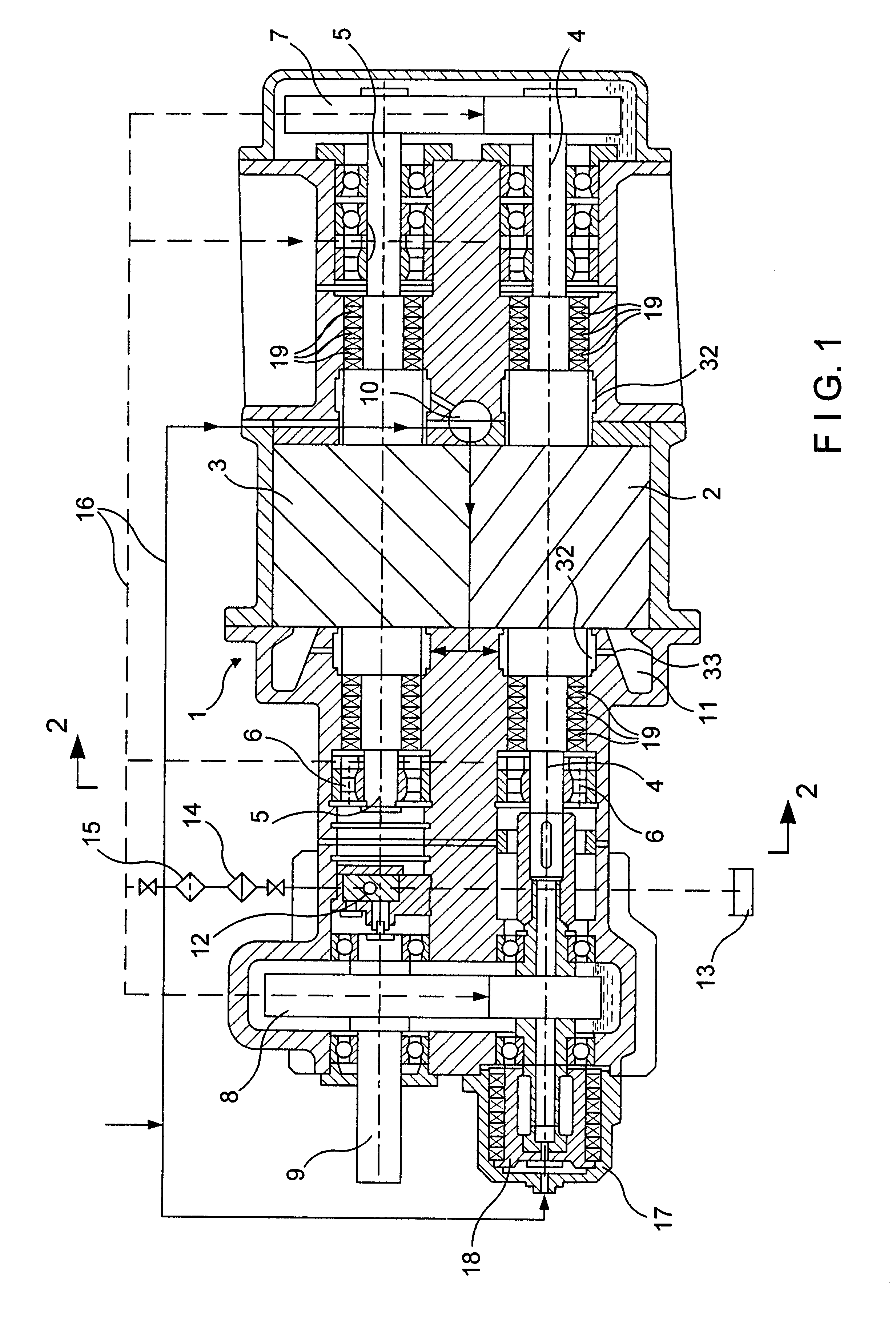
piston 18, connected with the shaft 4, develops the force opposing axial forces produced by interaction of screws 2 and 3. During the transformation of energy of the steam into
mechanical energy the steam under high pressure constantly moves in a space 32 (FIG. 2) of the device for an equilibration of forces in the bearing 6. In spaces 32, placed along a lateral area of the shafts 4 and 5 opposite the direction of the forces on the side of screws, by the pressure the steam on the shaft a radial forces "F", compensating the forces and thus unloading, the bearings 6 in these sites. Besides, steam coming through the throttling channels 33 from the space 32 into the intermediate chamber 34 and further into the outlet branch pipe 11 causes condensation. The liquid, formed during the
steam condensation, fills any clearances, reducing the probability of its penetration in a zone of the bearings while unloading the bearings.
The mechanism of a forced discharge of the steam and / or oils achieves stable discharge of the oil and steam. According to the variant represented in FIG. 4, while rotation of the shaft with the screws 2 or 3 opposite directed
helical gooves executed on the shaft, operating as inclined Archimedian screw pumps, draw in the air (represented by the arrow with points) from an atmosphere through the channel, direct a
stream of air in one groove on penetrated oil and in other groove--to steam and condensate, and transport the oil to hydraulic reservoir 13 via clearances 25 and channels 26, and steam and condensate via channels 23--into the atmosphere. Thus the reliable isolation of oil and steam is created.

