Micro-scanning multislit confocal image acquisition apparatus

a multi-slit, confocal image technology, applied in the direction of optical radiation measurement, instruments, spectrometry/spectrophotometry/monochromators, etc., can solve the problems of two-dimensional array type image acquisition apparatus with a problem of speckles, two-dimensional array type confocal image acquisition apparatus cannot solve the problem of speckles, and the effect of reducing the effect of speckles

Inactive Publication Date: 2001-09-11
TAKAOKA ELECTRIC MFG
View PDF2 Cites 87 Cited by
  • Summary
  • Abstract
  • Description
  • Claims
  • Application Information

AI Technical Summary

Benefits of technology

is to provide a non-scanning confocal image acquisition apparatus for measuring the shape of the surface of an object which apparatus does not have blind regions between illumination spots and can significantly reduce the effect of speckles.

Problems solved by technology

However, a two-dimensional array type image acquisition apparatus has a problem of speckles.
Since a confocal imaging system is basically a coherent imaging system and illumination light shone on the surface of the object has a high coherency within each spot, the light reflected from each spot interferes to cause speckles in and around the corresponding pinhole of the pinhole array if there are inequalities in the surface within the spot area.
Such speckles have a very bad effect on height measurement.
There is another problem in addition to the problem of speckles.
On the other hand, a two-dimensional array type confocal image acquisition apparatus cannot measure such a projection if it is located between illumination spots.
An image acquisition apparatus using an ordinary image-forming optical system and a two-dimensional arrayed photodetector such as a CCD camera can measure even the top part of the balls smaller than a pixel, though not accurately.
On the other hand, a two-dimensional array type confocal image acquisition apparatus cannot measure this unless an illumination spot is directed onto it.
In brief, a conventional two-dimensional array type confocal image acquisition apparatus has a problem inasmuch as it cannot measure a small object because of blind regions between illumination spots.
In addition to the above problem that a small object cannot be measured, blind regions between illumination spots cause another problem.
Subpixel-accuracy edge measurement, commonly possible when performing measurement of the edges of objects in images by image processing, is not possible by image processing of images obtained by a two-dimensional array type confocal image acquisition apparatus because of blind regions between illumination spots, or a low aperture ratio for pixels resulting from blind regions.

Method used


Image

  • Micro-scanning multislit confocal image acquisition apparatus
  • Micro-scanning multislit confocal image acquisition apparatus
  • Micro-scanning multislit confocal image acquisition apparatus

Examples


Embodiment Construction

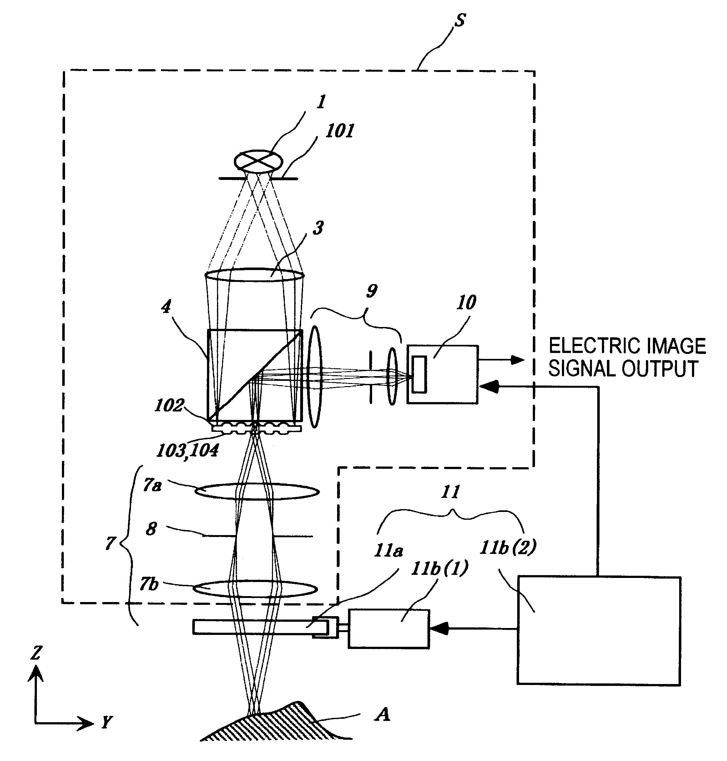
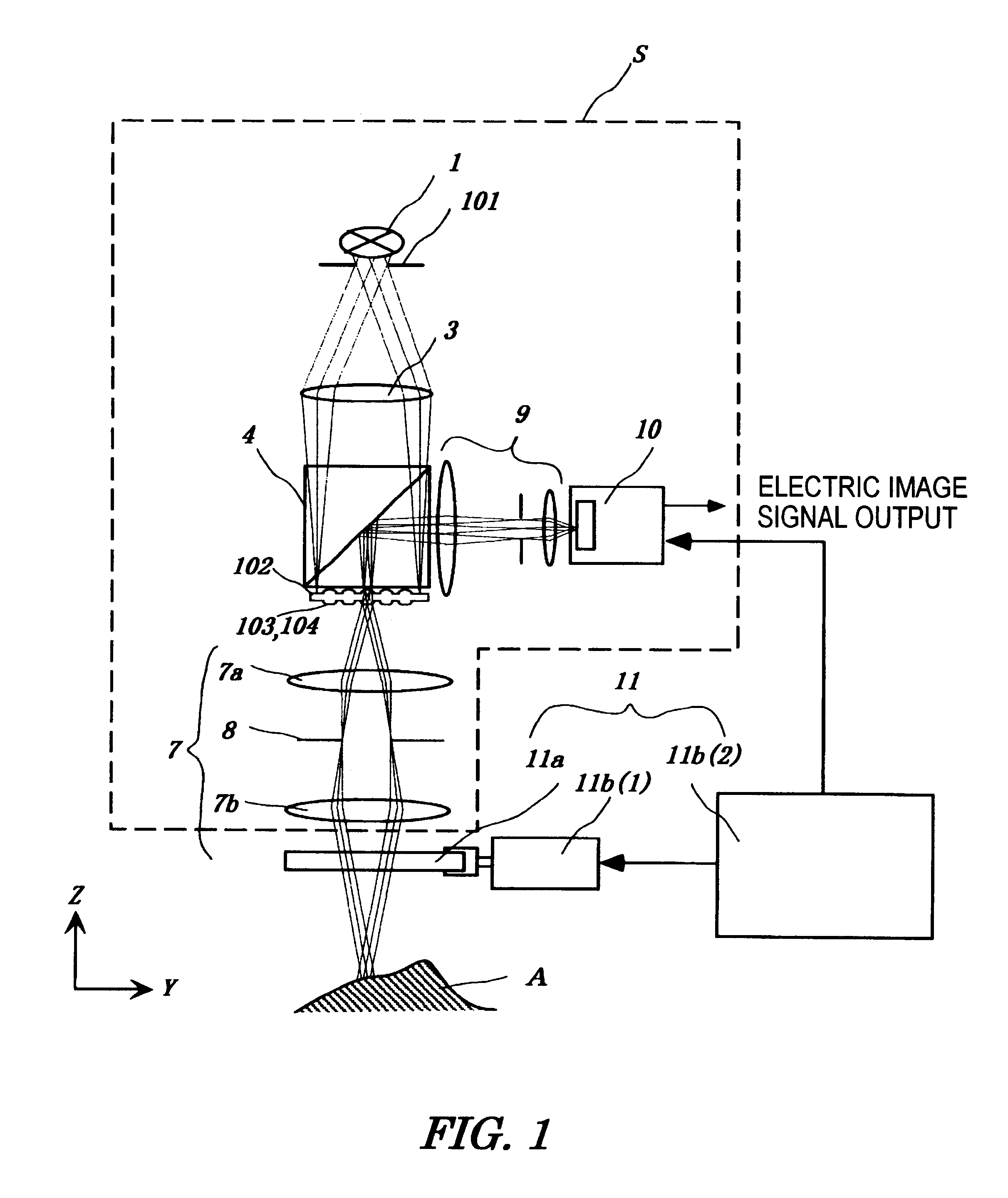
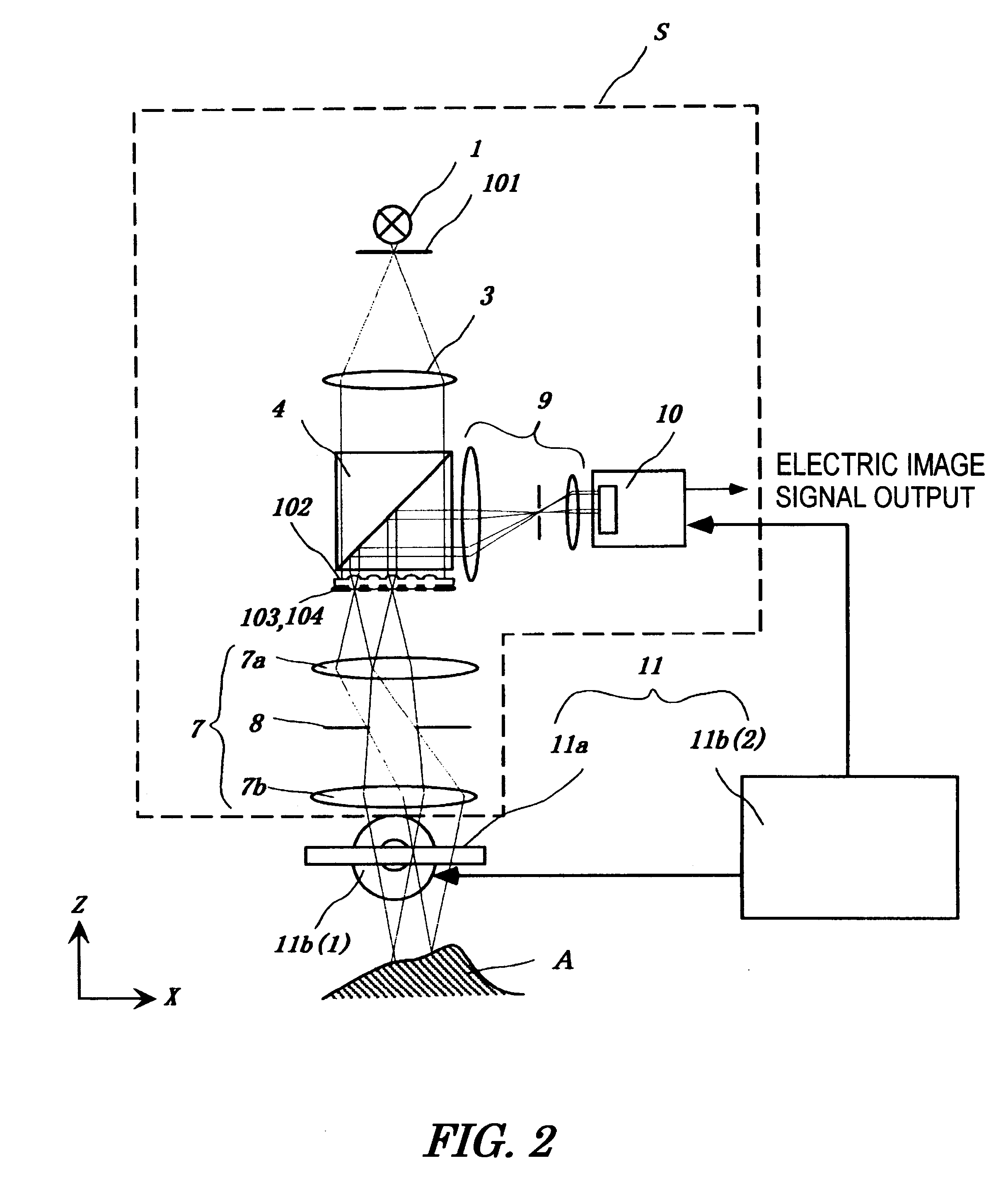
Preferred embodiments of the present invention are described below with reference to the drawings. FIGS. 1 and 2 show a first embodiment of the present invention. FIGS. 1 and 2 are side views of the first embodiment viewed from two directions at right angles to each other, in which some parts (a beam splitter 4, image re-forming lens 9, two-dimensional arrayed photodetector 10, object A, and controller 11b (2)) are drawn from the same direction in order to make the drawings easy to understand.

The apparatus of the present invention comprises a nonscanning multislit confocal image acquisition system S and a multislit-image microscanning mechanism 11. First, the nonscanning multislit confocal image acquisition system S is described below.

A light source 1 and a slit aperture 101 compose the illuminating light unit that emits light from the whole slit aperture 101 uniformly. Specifically, for example, the slit aperture 101 is formed by bundling one end of optical fibers in the shape of a...


PUM


Abstract

The micro-scanning multislit confocal image acquisition apparatus of the present invention is a confocal image acquisition apparatus that comprises a nonscanning multislit confocal image acquisition system using a slit array instead of a pinhole array and a multislit-image microscanning mechanism for moving the image of the slit array in a small back and forth motion with respect to the object during each exposure of the two-dimensional arrayed photodetector in one complete measurement. Microscanning the image of the slit array with an amplitude equal to half the distance between adjacent slits increase the aperture ratio of the pixels to 100 percent, reducing blind regions to zero. As a result, this apparatus can measure a small object that cannot be measured by a conventional nonscanning confocal image acquisition apparatus because of blind regions. Microscanning the image of the slit array can also reduce the effect of speckles, another problem of a conventional nonscanning confocal image acquisition apparatus, by averaging the reflected light passing through each aperture of the slit array.

Description

1. Field of the InventionThe present invention relates to the configuration of an image acquisition apparatus for measuring the shape of the surface of an object utilizing a two-dimensional array type confocal optical system.2. Description of the BackgroundThe position (hereinafter referred to as the height) of the object measured in the direction of the optical axis (hereinafter referred to as the z-axis direction) can be measured accurately by utilizing a confocal optical system. Before description of the prior art, the principle of measurement of height by a confocal optical system is explained. A basic configuration of the confocal optical system is shown in FIG. 8. Light emitted from a point light source 81 passes through a half-mirror 82 and is refracted by an objective lens 83 so as to converge onto the object. The light that is reflected by the object reenters the objective lens 83 and is caused to converge by the objective lens 83 and then diverted by the half-mirror 82 tow...

Claims


Application Information

Patent Timeline
Patent Type & Authority Patents(United States)
IPC IPC(8): G01B9/04G02B21/00G01B11/24G02B3/00G02B26/10
CPCG01B9/04G02B21/004G02B21/0036
Inventor ISHIHARA, MITSUHIRO
Owner TAKAOKA ELECTRIC MFG
Why Eureka
Try Eureka