Ferrite-free electrodeless fluorescent lamp

a fluorescent lamp and electrodeless technology, applied in the field of electric lamps, can solve the problems of reducing the lamp efficacy, restricting the lamp size, and the lamp with a coil outside is not attractive aesthetically, so as to achieve efficient coupling and minimize the interference of the coil

Inactive Publication Date: 2001-09-11
MATSUSHITA ELECTRIC WORKS LTD
View PDF12 Cites 38 Cited by
  • Summary
  • Abstract
  • Description
  • Claims
  • Application Information

AI Technical Summary

Benefits of technology

Yet another object of the present invention is to locate an induction coil to minimize interference of the coil with the lamp radiation.
A further object of the present invention is to position the coil so as to provide the efficient coupling with the lamp plasma.
Another object of the present invention is to design a lamp with the coil so the fixture does not affect coil operation, thereby allowing the use of a lamp with different fixtures, but with the same matching network without changing the lamp operational conditions.
Another object of the present invention is to design an electrodeless ferrite-free lamp that is easy to manufacture and of low cost.

Problems solved by technology

The lamp with a coil outside is not aesthetically attractive.
The introduction of the reentrant cavity reduces the volume of the envelope filled with the plasma which results in a decrease of the lamp efficacy.
However, such approach also has a drawback in that it is difficult to manufacture lamps with a large bottom diameter, which restricts the lamp size.
The increase of I.sub.coil leads to the increase of coil power losses, P.sub.loss,
The increase of coil power losses reduces lamp power efficiency and, hence, lamp efficacy.
Moreover, the increase of lamp power to 100-200 W or higher requires the increase of the envelope diameter and the cavity length that makes cooling of the ferrite core and the coil very difficult.
The ferrite core is relatively expensive, and it requires special ferrite preparation of two thoroughly polished cuts and brackets to keep these surfaces firmly together.
Also, the power loss in the coil increases as the number of turns decreases.
When the lamp is operated at lower frequency of 2-3 MHz, and lower, the coil with one turn consumes a considerable amount of RF power, making the lamp inefficient.

Method used


Image

  • Ferrite-free electrodeless fluorescent lamp
  • Ferrite-free electrodeless fluorescent lamp
  • Ferrite-free electrodeless fluorescent lamp

Examples


third embodiment

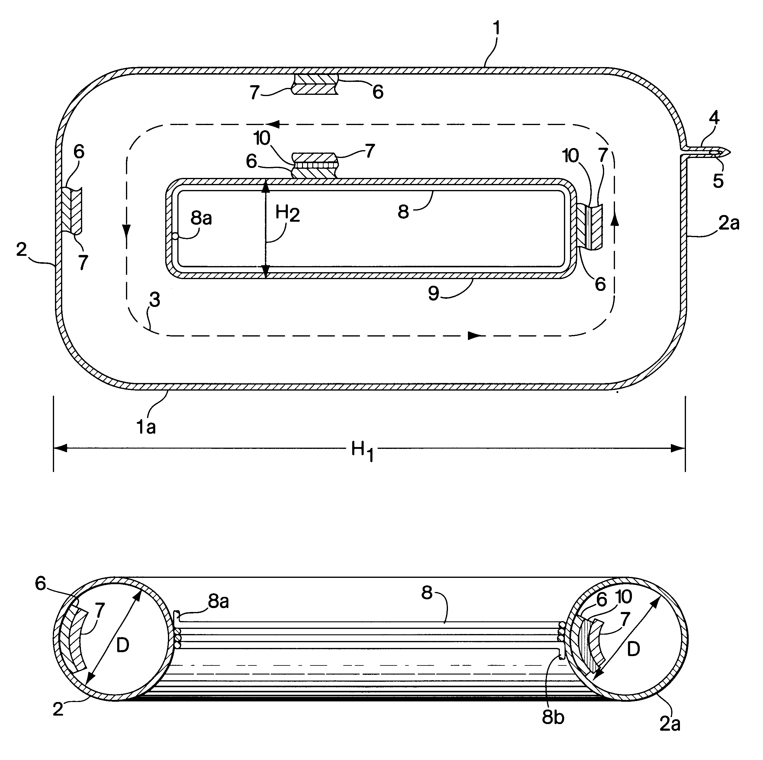
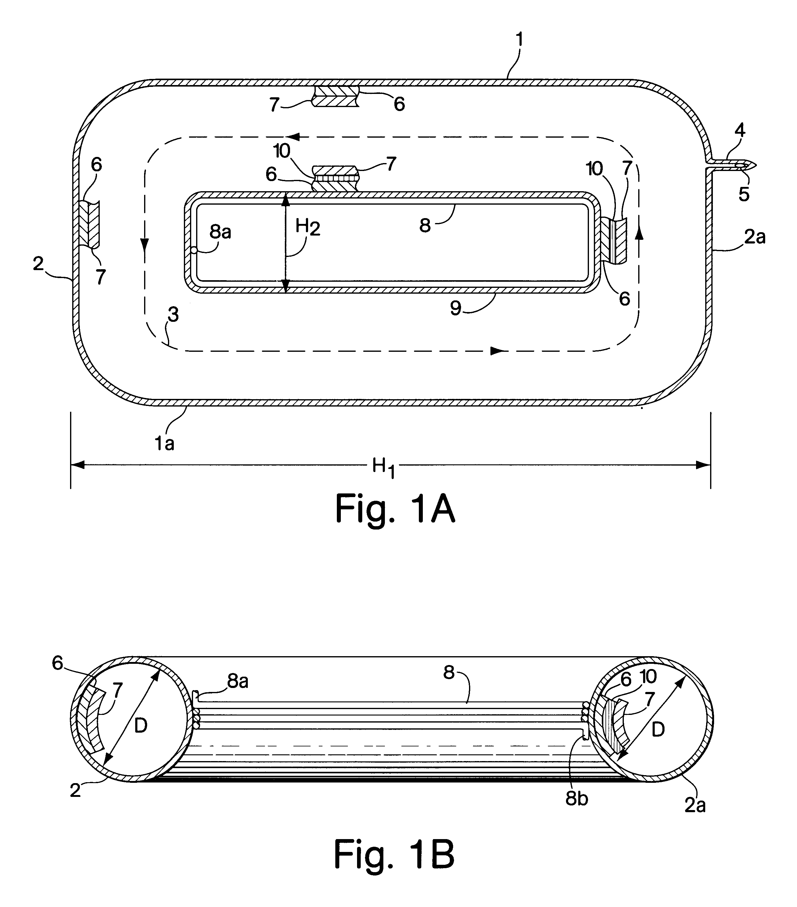
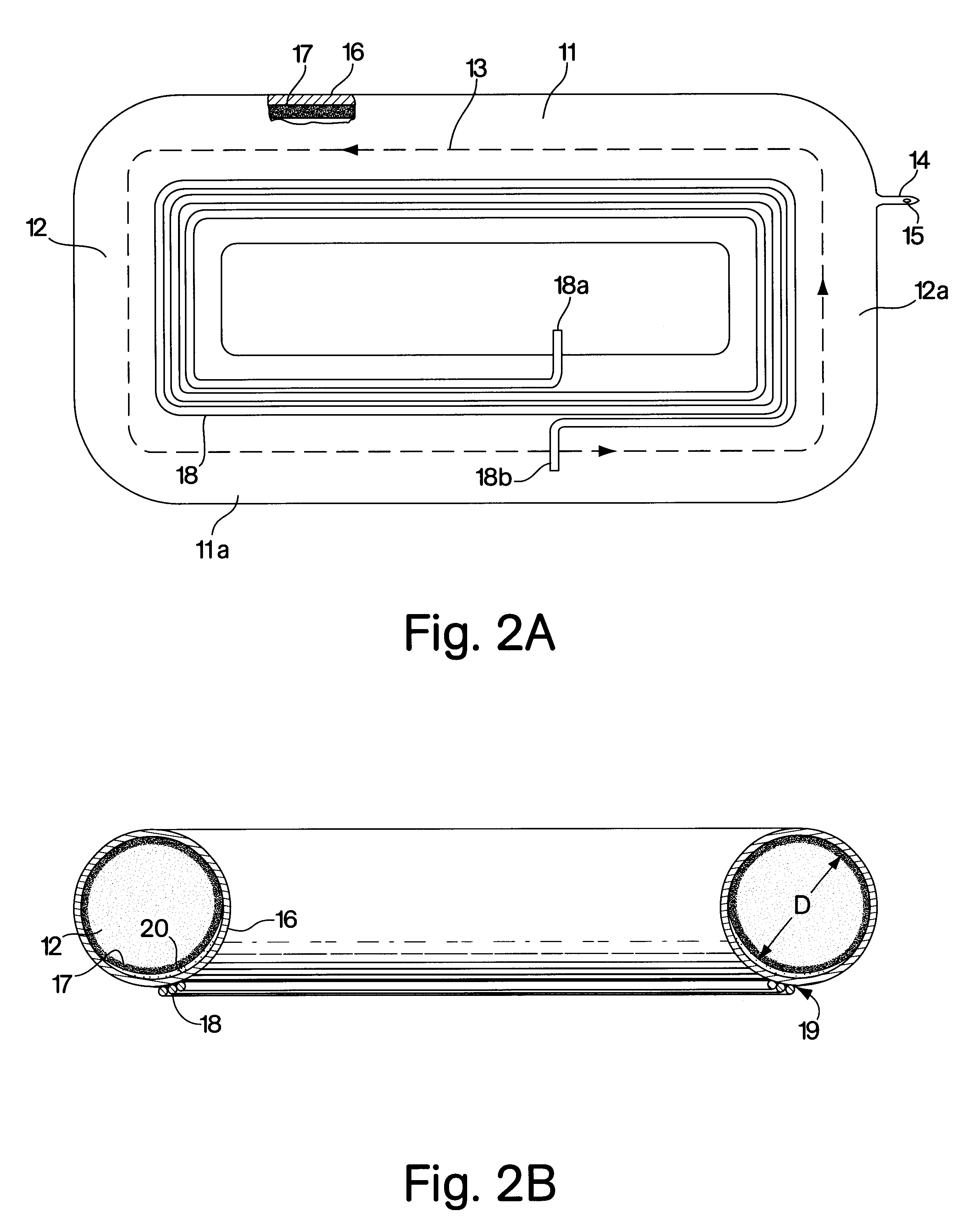
the present invention is shown in FIG. 2. The envelope of the lamp has rectangular shape and is made from glass tubes 11 and 12 of the same (or close) diameter. The tubes are connected to each other forming a closedloop path 13 for the discharge electric field and discharge current. The envelope is filled with inert gas and mercury vapor pressure that is controlled by the mercury amalgam or dispenser 15 positioned in the tubulation 14. The protective coating 16 and phosphor coating 17 are the same as in FIG. 1.

The induction coil 18 is disposed on the one of the outer surfaces 19 of the envelope as it is shown in FIG. 2. The inner surface 19 of the envelope that is adjacent to the coil 18 is coated with the reflective coating 20 made from Al.sub.2 O.sub.3 that works in the same manner as it is described in FIG. 1. Two coil leads 18a and 18b connect the coil 18 with the conventional matching network (not shown).

The envelope of the lamp of the fourth embodiment of the present invention...


PUM


Abstract

An electrodeless fluorescent lamp comprises a glass closed-loop envelope filled with inert gas and mercury vapor at pressure of 0.1-5 torr. An induction coil of few turns and made from Litz wire is disposed on the outer surface of the lamp inside of the closed-loop envelope. A phosphor coating is disposed on the inner surface of the envelope surface and a reflective coating is disposed on the inner surface of the area adjacent to the induction coil.

Description

FIELD OF THE INVENTIONThis invention relates to electric lamps and, more specifically, to fluorescent electrodeless lamps operated at low and intermediate pressures without the use of ferrites at frequencies from 20 kHz to 200 MHz.BACKGROUND OF THE INVENTIONElectrodeless fluorescent lamps utilizing an inductively coupled plasma were found to have a high efficacy and lives which are longer than conventional fluorescent lamps that employ hot cathodes. The plasma that generates visible and UV light is induced in a glass (or quartz) envelope filled with inert gas such as argon, krypton at pressure of 0.1-2 torr and mercury vapor. To generate such a plasma at a frequency of 13.56 MHz, electrodeless lamps employ an induction coil positioned near the lamp envelope. The prior art teaches three basic approaches of coupling the induction coil and the lamp plasma at a frequency of 13.56 MHz.The most simple coupling method is wrapping the induction coil around the envelope which was disclosed i...

Claims


Application Information

Patent Timeline
Patent Type & Authority Patents(United States)
IPC IPC(8): H01J65/04
CPCH01J65/048
Inventor POPOV, OLEG
Owner MATSUSHITA ELECTRIC WORKS LTD
Why Eureka
Try Eureka