Superconducting magnet split cryostat interconnect assembly

a superconducting magnet and cryostat technology, applied in the direction of superconducting magnets/coils, magnetic bodies, container discharge methods, etc., can solve the problem of increasing the temperature of the magnet, and achieve the effect of adding strength

Inactive Publication Date: 2001-09-18
GENERAL ELECTRIC CO
View PDF11 Cites 38 Cited by
  • Summary
  • Abstract
  • Description
  • Claims
  • Application Information

AI Technical Summary

Benefits of technology

The high purity aluminum tube in the interconnect includes a flexible joint which in combination with a bellows on the outer stainless steel tube accommodates thermal contraction and expansion. Helium gas boiloff from the lower helium vessel is vented to the interior of the interconnect

Problems solved by technology

The isothermal members extend the ride-through period of magnet superconducting operation in the

Method used


Image

  • Superconducting magnet split cryostat interconnect assembly
  • Superconducting magnet split cryostat interconnect assembly
  • Superconducting magnet split cryostat interconnect assembly

Examples


Embodiment Construction

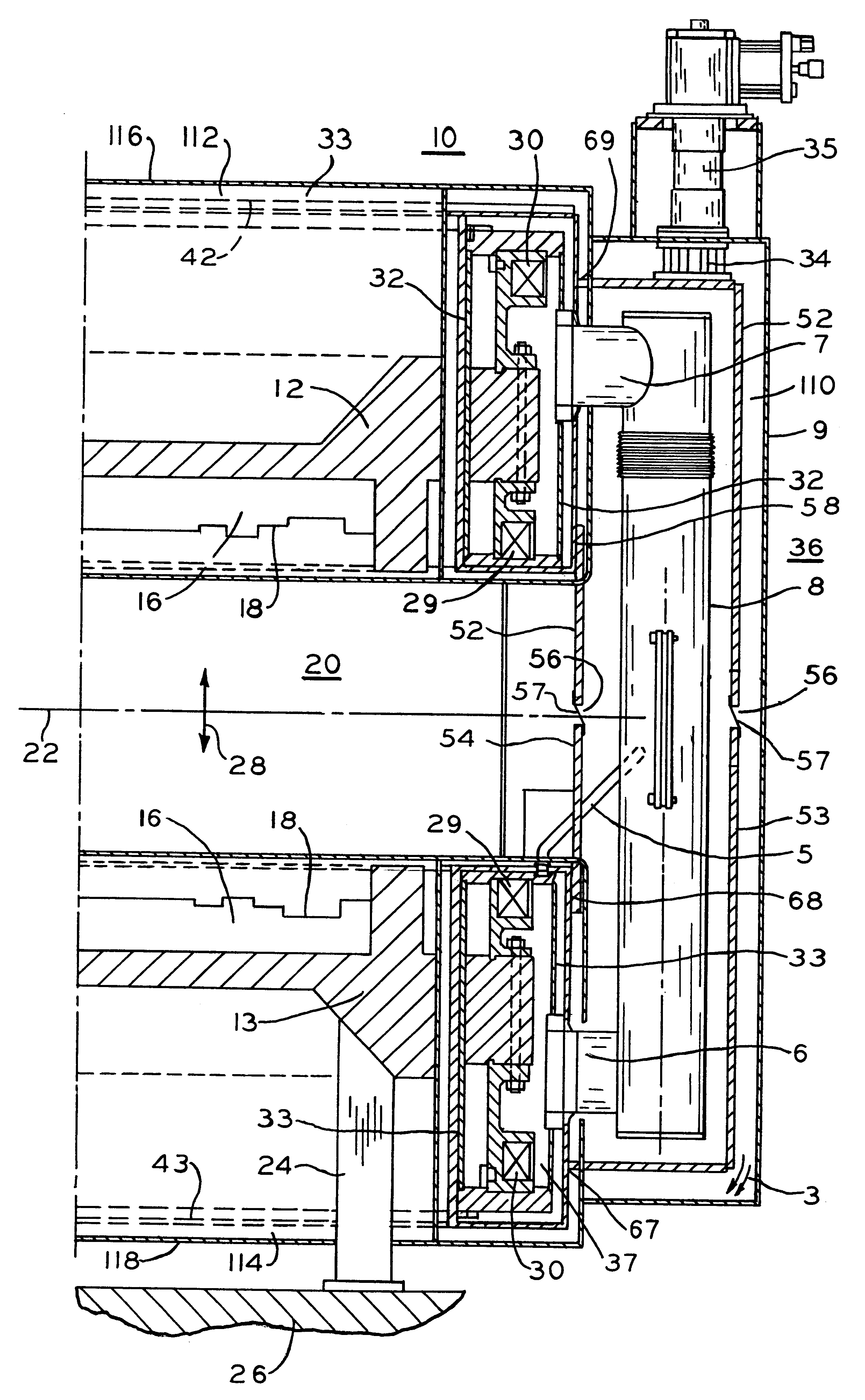
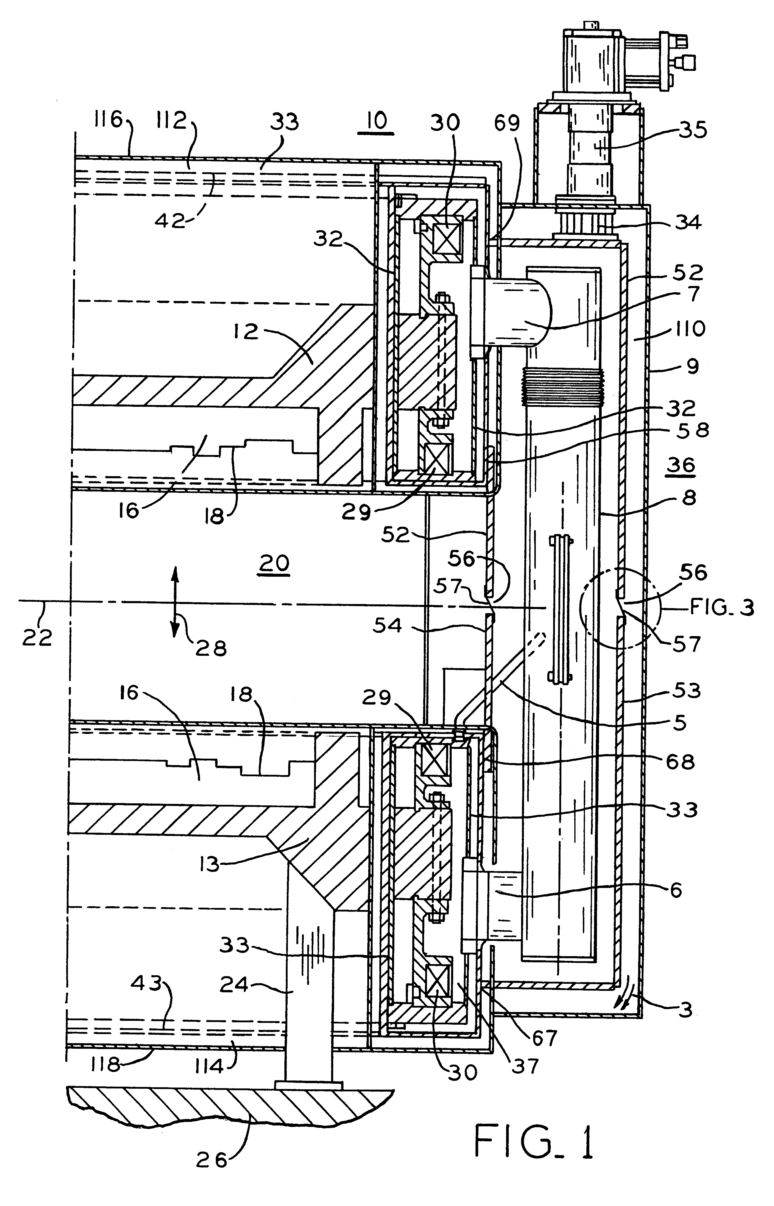
Referring first to FIG. 1, open architecture superconducting magnet 10 includes spaced parallel pole pieces 12 and 13 separated and supported at one end by a pair of non-magnetic connecting members or posts shown generally as 14. Pole pieces 12 and 13 are of ferromagnetic material such as iron. Pole faces 16 are shaped 18 to improve magnetic field homogeneity within imaging region 20 along axis 22 of superconducting magnet 10. Supports 24 secure magnet 10 to floor 26.

The main magnetic field, Bo, indicated generally by arrow 28 within imaging region 20 is generated by magnet coils shown generally as 29 and 30 within pressure or cryogen vessels 32 and 33. Magnetic field shimming apparatus such as correction coils (not shown) within cryogen vessels 32 and 33 and / or passive shims in external shim drawers (not shown) compensate for magnetic field inhomogeneities within imaging region 20 in the manner well known in the art. liquid helium shown generally as 37 is a suitable cryogen for use...


PUM


Abstract

A multi purpose interconnect assembly between upper and lower helium vessels in a recondensing superconducting magnet to provide isothermal connections to extend the ride-through period, and to provide for helium liquid and gas passage, electrical interconnections, and to accommodate differential thermal contraction and expansion.

Description

BACKGROUND OF INVENTIONThis invention relates to a split cryostat superconducting magnet, and more particularly to the interconnect assembly between the magnets.As is well known, a superconducting magnet can be made superconducting by placing it in an extremely cold environment, such as by enclosing it in a cryostat or pressure vessel containing liquid helium or other cryogen. The extreme cold ensures that the magnet coils can be made superconducting, such that when a power source is initially connected to the coil (for a relatively short period) current continues to flow through the coils even after power is removed due to the absence of resistance, thereby maintaining a strong magnetic field. Superconducting magnets find wide application in the field of Magnetic Resonance Imaging (hereinafter MRI).Another problem encountered by conventional and early MRI equipments is that they utilize solenoidal magnets enclosed in cylindrical structures with a central bore opening for patient ac...

Claims


Application Information

Patent Timeline
IPC IPC(8): F17C13/00F17C3/00F17C3/08
CPCF17C3/085H01F6/04G01R33/3804G01R33/3806F17C2265/033G01R33/3802F17C2270/0509
Inventor ECKELS, PHILLIP WILLIAMHACKETT, RICHARD THOMASHAYWORTH, GREGORY F.HUANG, XIANRUIGINFRIDA, CLIFFORD J.LEHMANN, GREGORY ALANSCATURRO, JR., JOHNXU, BU-XIN
Owner GENERAL ELECTRIC CO
Why Eureka
Try Eureka