Method and device for centering a dressing tool in the thread of a grinding worm

a technology of grinding worms and dressing tools, which is applied in the direction of grinding machines, gear cutting machines, gear teeth, etc., can solve the problems of time-consuming and skill-intensive methods, and achieve the effect of considerably less consumption

Inactive Publication Date: 2001-09-18
REISHAUER
View PDF5 Cites 37 Cited by
  • Summary
  • Abstract
  • Description
  • Claims
  • Application Information

AI Technical Summary

Benefits of technology

The object of the invention described below is to specify a method and a device, by means of which the centering of the dressing tool proceeds automatically and consumes considerably less time.

Problems solved by technology

This method is time-consuming and requires skill, since the contact between dressing tool and grinding worm can often only be detected with difficulty because of poor accessibility of the engagement point, and the centering of the dressing tool, on account of the small dressing infeed amount, in particular in the case of CBN grinding worms (abrasive grains of cubic boron nitride), has to be very accurate.

Method used


Image

  • Method and device for centering a dressing tool in the thread of a grinding worm
  • Method and device for centering a dressing tool in the thread of a grinding worm

Examples


Embodiment Construction

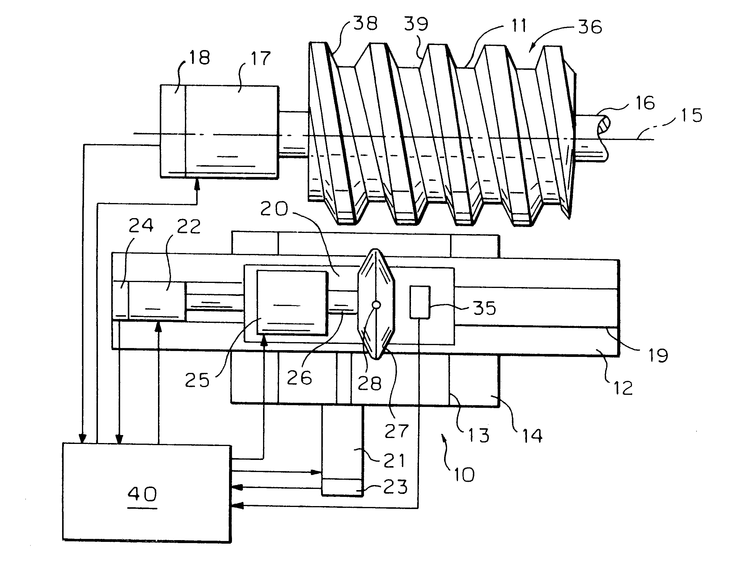
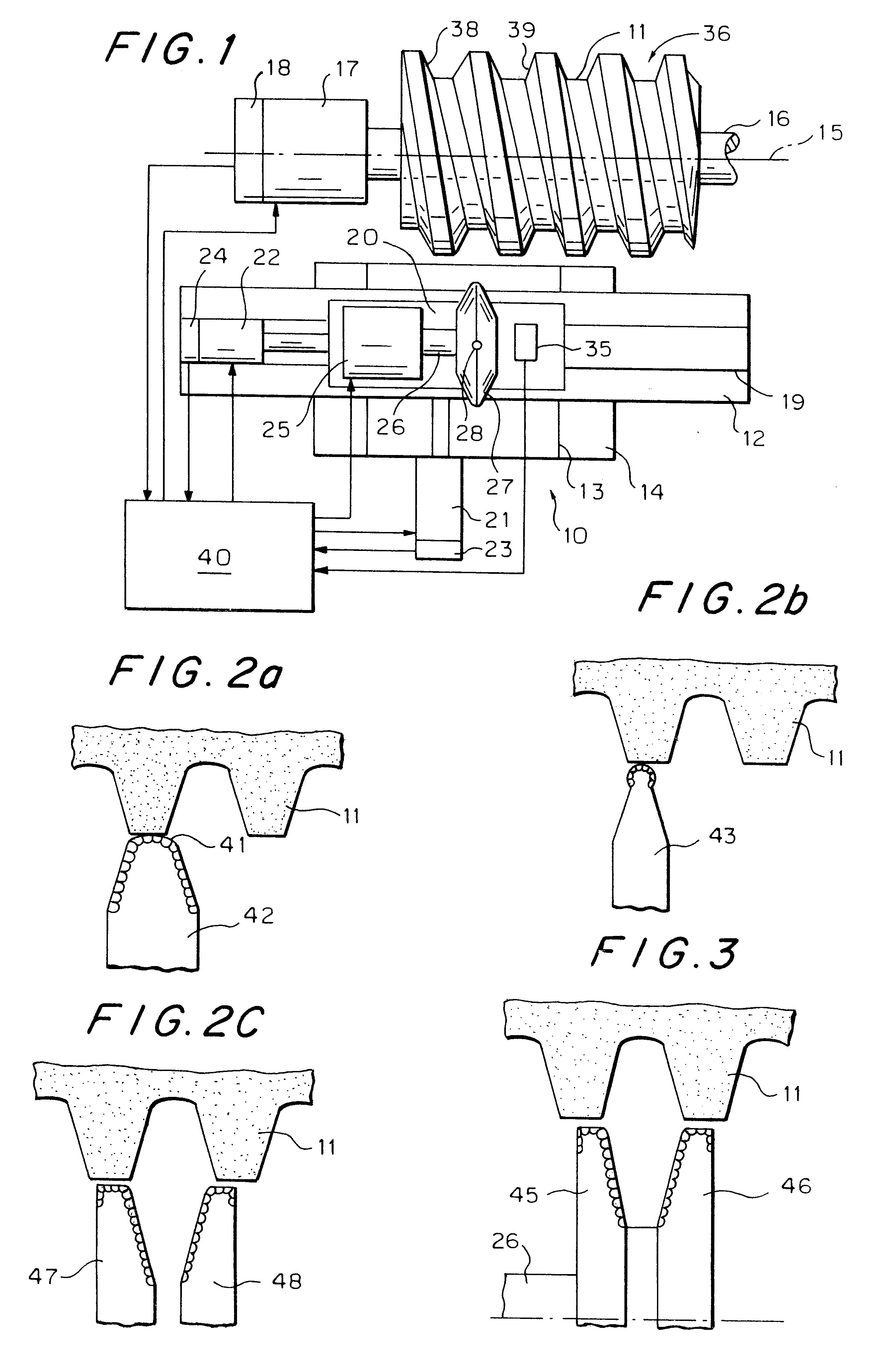
FIG. 1 shows a dressing device 10 for dressing a grinding worm 11. The dressing device may be designed, for example, according to DE-A 197 06 867.7. It comprises a cross slide, a first slide 12 being displaceable along a guide 13 of a machine base 14 perpendicularly to the axis 15 of the grinding spindle 16. The grinding worm 11 is mounted on the spindle 16, which is driven by a motor 17 and is connected to a rotary encoder 18. On the slide 12, a second slide 20 is displaceable guided in a guide 19 parallel to the axis 15. The slides 12, 20 are each displaceable by a respective motor 21, 22 with displacement feedback 23, 24. Mounted on the slide 20 is the dressing motor 25, which drives the dressing spindle 26, on which the dressing disc 27 is mounted. The dressing disc 27 may be additionally pivotable about an axis 28 perpendicular to the direction of the guides 13, 19 (see DE-A 197 06 867.7).

In addition, an acoustic sensor 35 is mounted on the slide 20. All the servomotors 17, 21,...


PUM

PropertyMeasurementUnit
outer circumferenceaaaaaaaaaa
circumferenceaaaaaaaaaa
diameteraaaaaaaaaa

Abstract

In a first step for the purpose of precentering, the dressing too; (27), without axial movement, is brought into contact with the circumference of the rotating grinding worm (11), and those rotary-angle positions of the grinding worm (11) at which the overrunning of the thread gap (36) starts of ends are determined by means of an acoustic-sensor signal and the shaft-angle encoder (18) of the grinding spindle (16). In a second step for the purpose of precision centering, the dressing tool (27) fed into the thread gap (36) is brought into contact with the left-hand and right-hand tooth flanks (38, 39) by axial displacement. In this case, the axial infeed is stopped by means of the acoustic-sensor signal, and the exact grinding-worm thread center is calculated from the contact positions of the dressing tool (27) achieved.

Description

Prior ArtOn account of its high quality and productivity, continuous generation grinding of gears is considered to be one of the hard finishing processes, which have also become widespread in the large-scale manufacture of gears. The grinding tool, the so-called grinding worm, is a cylindrical grinding wheel which has at its circumference a rack-like worm-shaped profile, which during grinding can be brought into meshing engagement with the premachined workpiece toothing. The grinding worms are profiled with rotating dressing discs which are coated with hard-material grains, engaged in the grinding worm thread during the dressing and, while in contact with one flank or simultaneously with both flanks of the grinding worm thread, is displaced in accordance with the pitch of the latter parallel to the grinding-wheel axis.When re-using a grinding worm which is already profiled or when using a new rough-profiled grinding worm, the task of the operator, as a requirement for the subsequent...

Claims


Application Information

Patent Timeline
Patent Type & Authority Patents(United States)
IPC IPC(8): B23F23/00B23F23/12B24B53/06B24B53/14B24B53/085B24B53/075B24B53/12B23F19/12B24B53/00
CPCB23F23/1225B24B53/14B24B53/085B24B53/075
Inventor THYSSEN, WOLFGANG
Owner REISHAUER
Why Eureka
Try Eureka