Method and apparatus for controlling numerically controlled machine tool

a numerical control and machine tool technology, applied in the direction of electric programme control, program control, instruments, etc., can solve the problems of machine stoppage, machining operation, and often over-rated current supplied for the operation of feed motors during machining operations

Inactive Publication Date: 2001-09-18
MAKINO MILLING MASCH CO LTD
View PDF17 Cites 53 Cited by
  • Summary
  • Abstract
  • Description
  • Claims
  • Application Information

AI Technical Summary

Problems solved by technology

However, the machining conditions required for the numerically controlled machine tool, such as implementing of quick acceleration or deceleration of the rapid feed and the machining feed, machining of workpiece stock lacking good machinability, and acquiring of a complicated machined contour in a workpiece are so severe that the electric current supplied for the operation of the feed motors often exceeds the rated current during a machining operation with a large machining load.
Consequently, the drive means including the servo amplifier and the feed motor exceeds the tolerable temperature, with the occasional result that the machine is stopped, by an alarm, to stop the machining operation.
Once the machine tool stops during the machining operations, not only the machining efficiency is deteriorated but also a generation of defective workpiece occurs, and in the case of unmanned operations, the machine tool is left stationary for a long time before the operation is restored by the operator.
The resulting problem is that, especially in the case where a numerically controlled machine tool is operated as a high-speed machine for a long time, the drive means is not necessarily properly controlled.
Another problem is the lack of versatility arising from the use of the special means called the disturbance estimating observer means.
In the method of controlling the robot drive motor for the shortest possible length of time disclosed in Japanese Unexamined Patent publication (Kokai) No. 0-91025, however, the robot regenerating operation is carried out several times by repeating the operating cycles, from which the thermal limitation, i.e. the tolerable range in an amount of heat generation of the drive motor for each axis is determined.
Therefore, in an application of this technique to the machine tool, for example, the operating cycle is repeated and the heat generation of the drive motor is monitored each time the machining condition or the machining load undergoes a change, thereby making it difficult to accomplish an efficient machining operation.
Further, the machining operation by a numerically controlled machine tool often lasts for a long time, and often has an extremely long operating cycle as compared with the operating cycle of industrial robots.
Therefore, it is considered inadequate to use the control method of Japanese Unexamined Patent publication (Kokai) No. 9-91025 described above for determining the thermal condition of the drive means for the machining operation of a numerically controlled machine tool.

Method used


Image

  • Method and apparatus for controlling numerically controlled machine tool
  • Method and apparatus for controlling numerically controlled machine tool
  • Method and apparatus for controlling numerically controlled machine tool

Examples


first embodiment

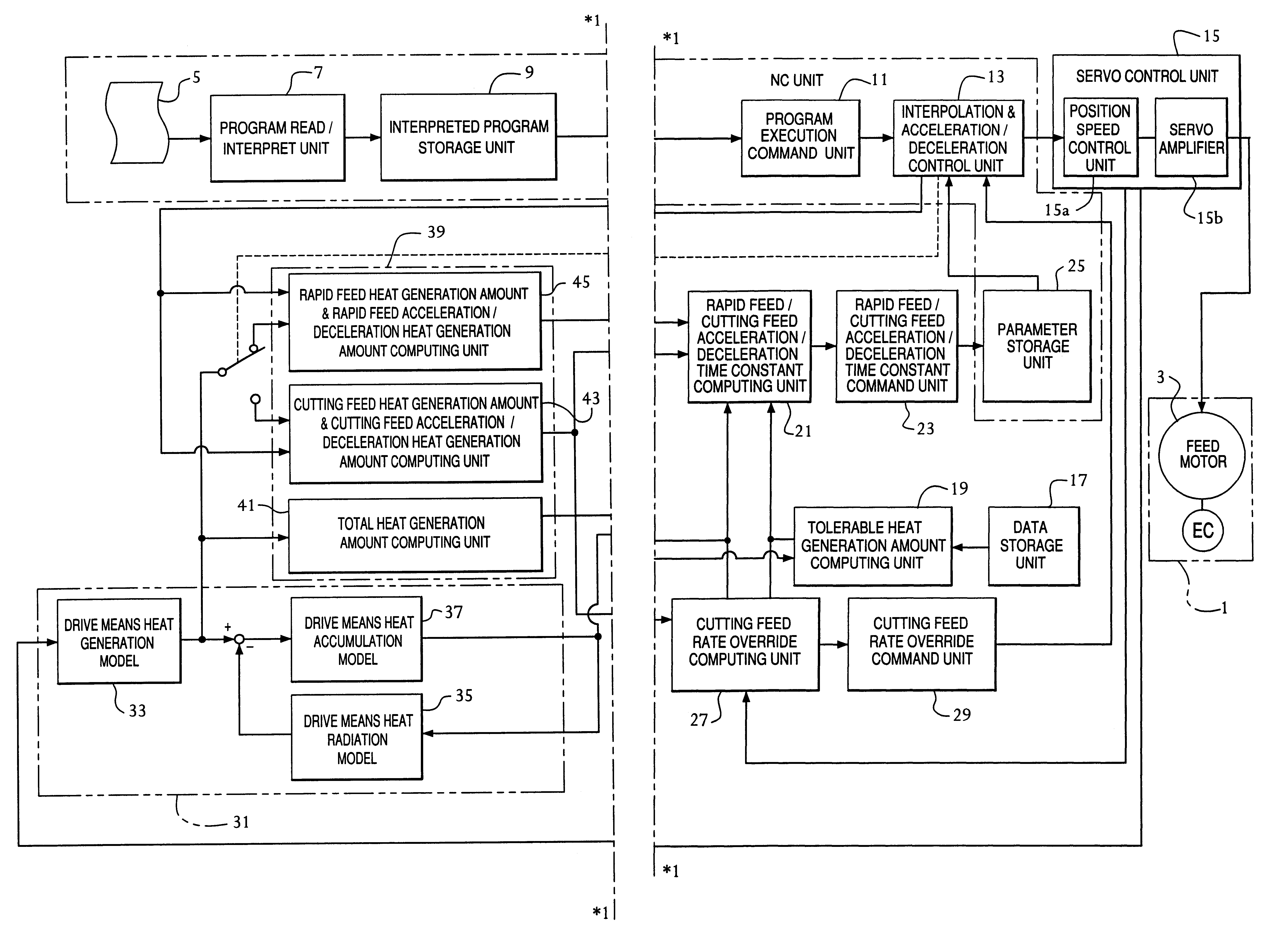
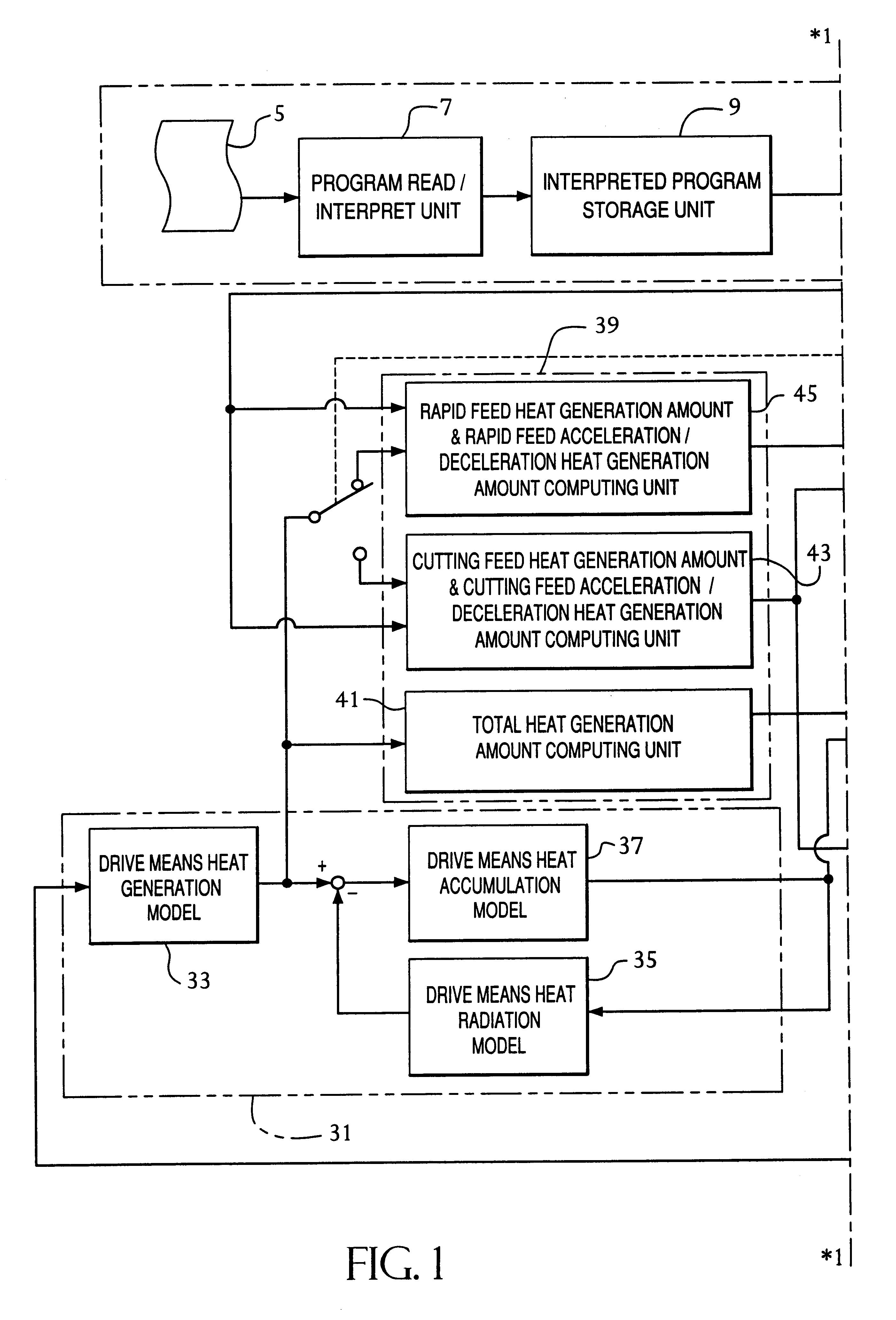
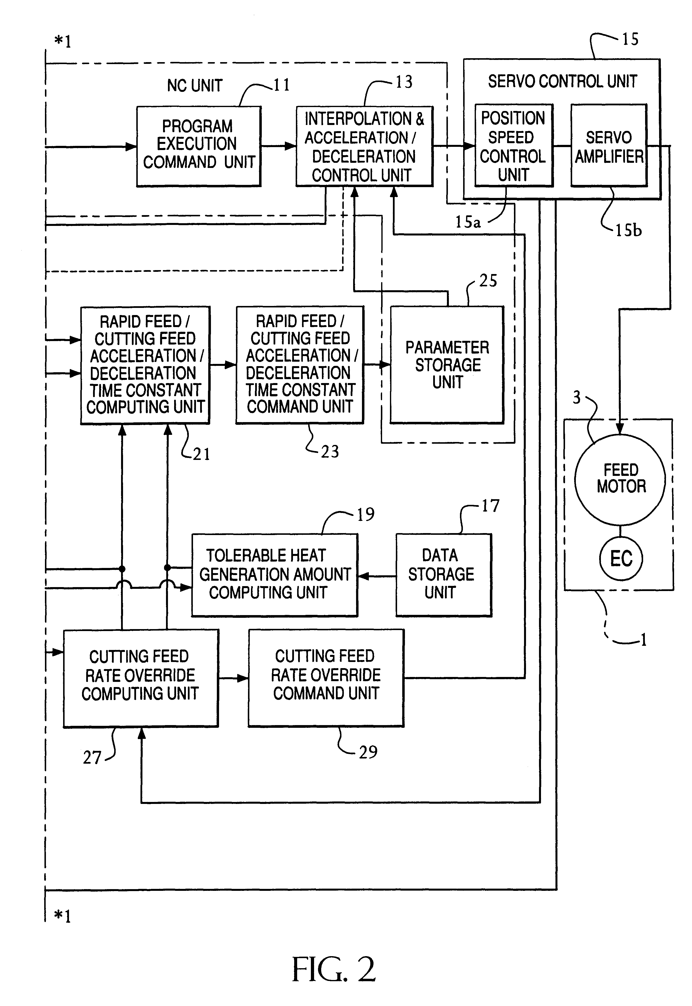
First, by referring to the block diagrams of FIGS. 1 and 2 showing the invention, a configuration is shown for numerically driving and controlling a plurality of feed axes, each being provided with a linear feed mechanism or a rotational feed mechanism of a numerically controlled machine tool 1. In this way, the numerically controlled machine tool 1 generally has a plurality of feed axes. One of the feed axes, shown as a representative, is driven by a feed motor 3 having a feed amount detection means EC including a pulse coder, for example, for detecting the amount of feed along a feed axis. An NC program 5 includes sequentially coded operation commands to be performed by the numerically controlled machine tool 1. The NC program 5 is read and interpreted by a program read and interpret unit 7, and temporarily stored in an interpreted program storage unit 9 forming a buffer unit. A program execution command unit 11 connected to the interpreted program storage unit 9 receives the prog...

second embodiment

The configuration of the invention will be explained hereinbelow with reference to FIGS. 3 and 4.

A difference of the second embodiment from the above-described first embodiment lies in the configuration and the method of computation of the acceleration / deceleration time constants for the two modes of rapid feed and cutting feed. For this reason, the function units having the same or similar configuration as or to those of the preceding embodiments are designated by the same reference numerals, respectively.

Specifically, according to the second embodiment, the rapid feed / cutting feed acceleration / deceleration time constant computing unit 21 has such a configuration as to receive the temperature data at each moment of the drive means from the drive means heat generation amount computing unit 31. On the other hand, the temperature condition of the drive means experimentally determined in advance for each of the feed modes is set and stored as set temperature data in the data storage un...

third embodiment

The third embodiment is different from the first and second embodiments in the configuration and the method for computing the acceleration / deceleration time constants in the two modes of rapid feed and cutting feed. The function units identical or similar to those included in the configuration of the first and second embodiments, therefore, are designated by the same reference numerals, respectively.

Specifically, the third embodiment is configured in similar manner to the previous embodiments, in that the current data or the torque command data for the feed shaft drive means fetched from the servo control unit 15 of the NC unit are input to the drive means heat generation amount computing unit 31 so that the temperature data of the drive means are computed by simulation. The third embodiment is also similar to the previous embodiments in that a drive means heat generation model 33 of the drive means heat generation amount computing unit 31 is provided with a feed heat generation amo...


PUM


Abstract

A method and an apparatus for controlling a numerically controlled machine tool, wherein the heat generation amount and the temperature of a drive unit including a servo amplifier 15b and a feed shaft motor 3 are computed by a drive unit heat generation amount computing unit 31 by simulation, and from the computed heat generation amount and the computed temperature, the total heat generation amount of the drive unit, the cutting feed heat generation amount, the cutting load heat generation amount, etc. are computed by a feed heat generation amount computing unit 39, so that the cutting feed rate override value of the numerically controlled machine tool 1 is computed by a cutting feed rate override computing unit 27 and effectuated by being output to a NC unit. Further, based on the temperature of the drive unit computed by a computing unit 31 or the temperature computed by a temperature data computing unit 47 or the temperature detected by a temperature detection sensor 49, etc., the proper values of the feed acceleration / deceleration time constants τ<SMALLCAPS>r < / SMALLCAPS>and τ<SMALLCAPS>c < / SMALLCAPS>are computed and output as a ratio with respect to the set and stored initial values τ<SMALLCAPS>r0 < / SMALLCAPS>and τ<SMALLCAPS>C0 < / SMALLCAPS>thereby to control the NC commanded rate. The overheating of the feed axis drive unit is prevented while at the same time improving the machining efficiency.

Description

The present invention relates generally to a method and an apparatus for controlling a numerically controlled machine tool or, in particular, to a method and an apparatus for controlling a numerically controlled machine tool wherein the machining operation is performed by numerically controlling the feed operation of a plurality of feed axes while preventing an alarm which otherwise might be issued due to the overheating of the drive means of each feed axis, thus making it possible to carry out the machining operation at as high a speed as possible to realize an improved machining efficiency. The above-described machine tool is not limited to a machine tool used only for cutting or grinding, but includes a punch press machine having a feed axis mechanism with a feed motor and a laser beam machine for machining a work with a high energy laser beam. The present invention is widely applicable to machine tools including these machines.PRIOR ARTConsideration will be given to a typical ma...

Claims


Application Information

Patent Timeline
Patent Type & Authority Patents(United States)
IPC IPC(8): G05B19/404G05B19/406B23Q15/12B23Q15/18G05B19/416
CPCG05B19/404G05B19/406G05B2219/49204
Inventor YOSHIDA, JUNTERAOKA, YOSHIKATSUMORI, NORIO
Owner MAKINO MILLING MASCH CO LTD
Why Eureka
Try Eureka