Circuit and method for limiting subthreshold leakage

a subthreshold leakage and circuit technology, applied in pulse manipulation, pulse technique, instruments, etc., can solve the problems of unpractical one-size-fits-all solution and the dissipation of attenuated charg

Inactive Publication Date: 2001-09-18
HEWLETT PACKARD DEV CO LP
View PDF6 Cites 6 Cited by
  • Summary
  • Abstract
  • Description
  • Claims
  • Application Information

AI Technical Summary

Benefits of technology

Certain embodiments of the invention are also capable of realizing the following advantages:
That is, the protection can track process parameters across manufacturing variations, track the behavior of the circuit being protected (i.e. can use a replica of the circuit prone to failure as the monitor), and allow robust use of circuit types that would otherwise fail due to CMOS manufacturing variations and non-ideal device characteristics.

Problems solved by technology

If the shift signal 27 remains high long enough, the subthreshold leakage can be severe enough to cause the latched charge to dissipate.
However, given the magnitude of variations present in CMOS circuit manufacturing, a one-size-fits-all solution is not practical.

Method used


Image

  • Circuit and method for limiting subthreshold leakage
  • Circuit and method for limiting subthreshold leakage
  • Circuit and method for limiting subthreshold leakage

Examples


Embodiment Construction

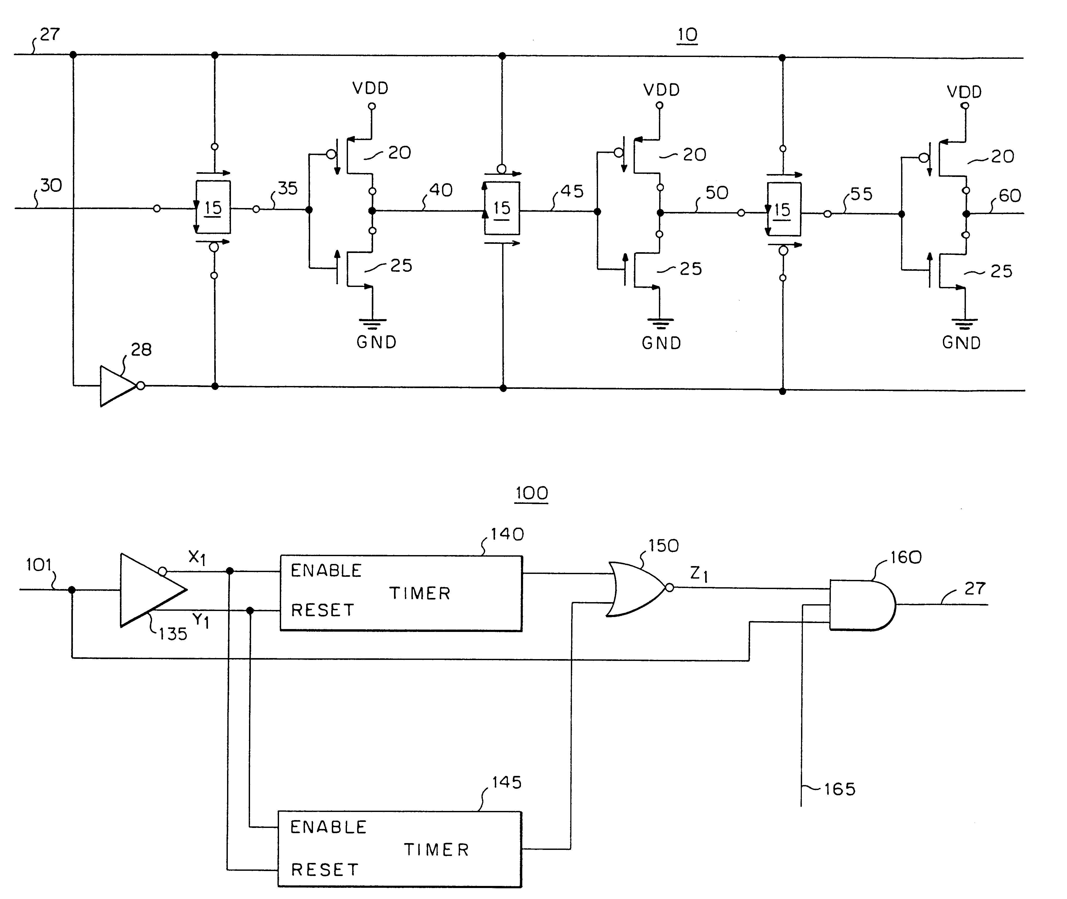
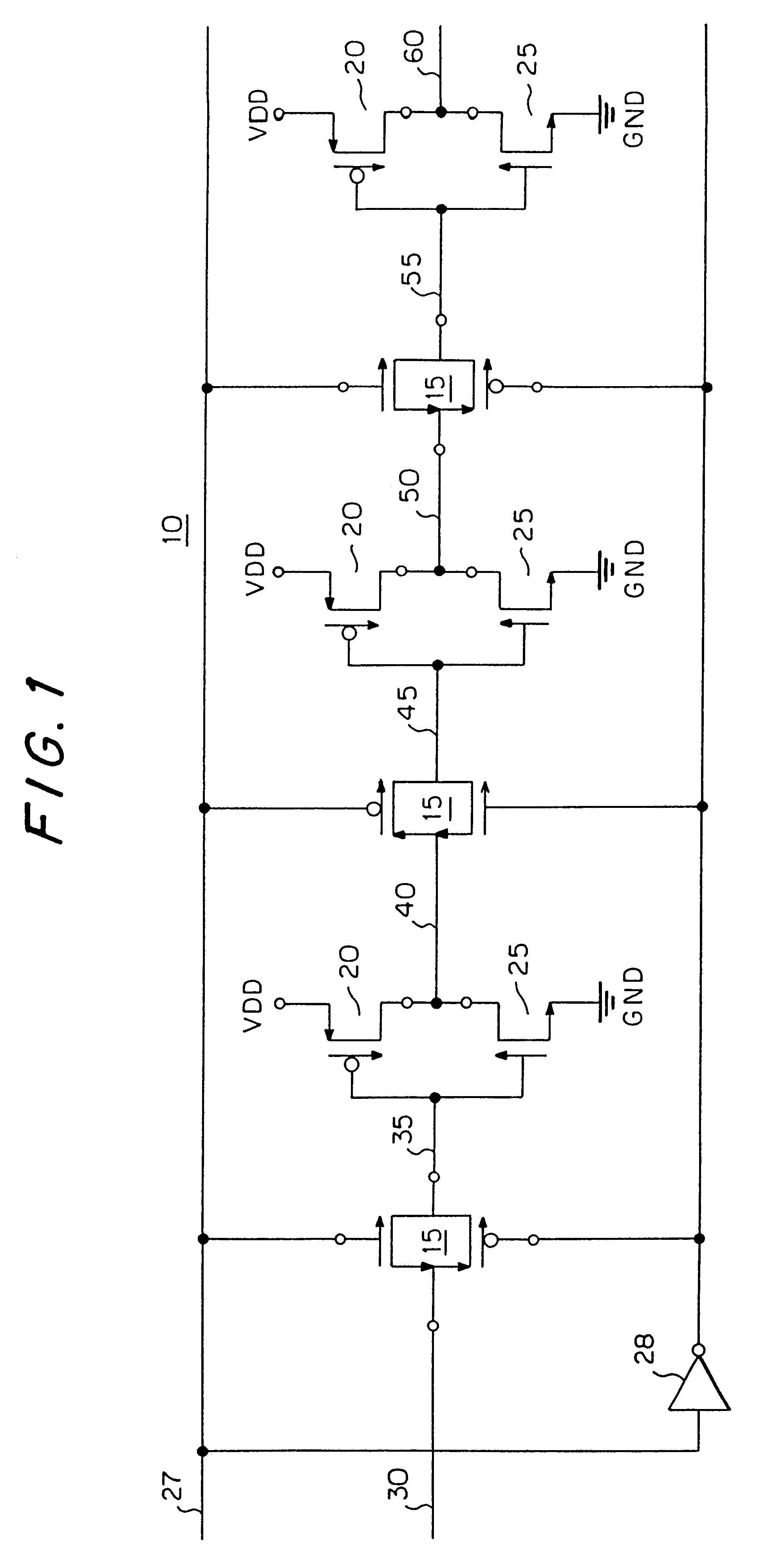
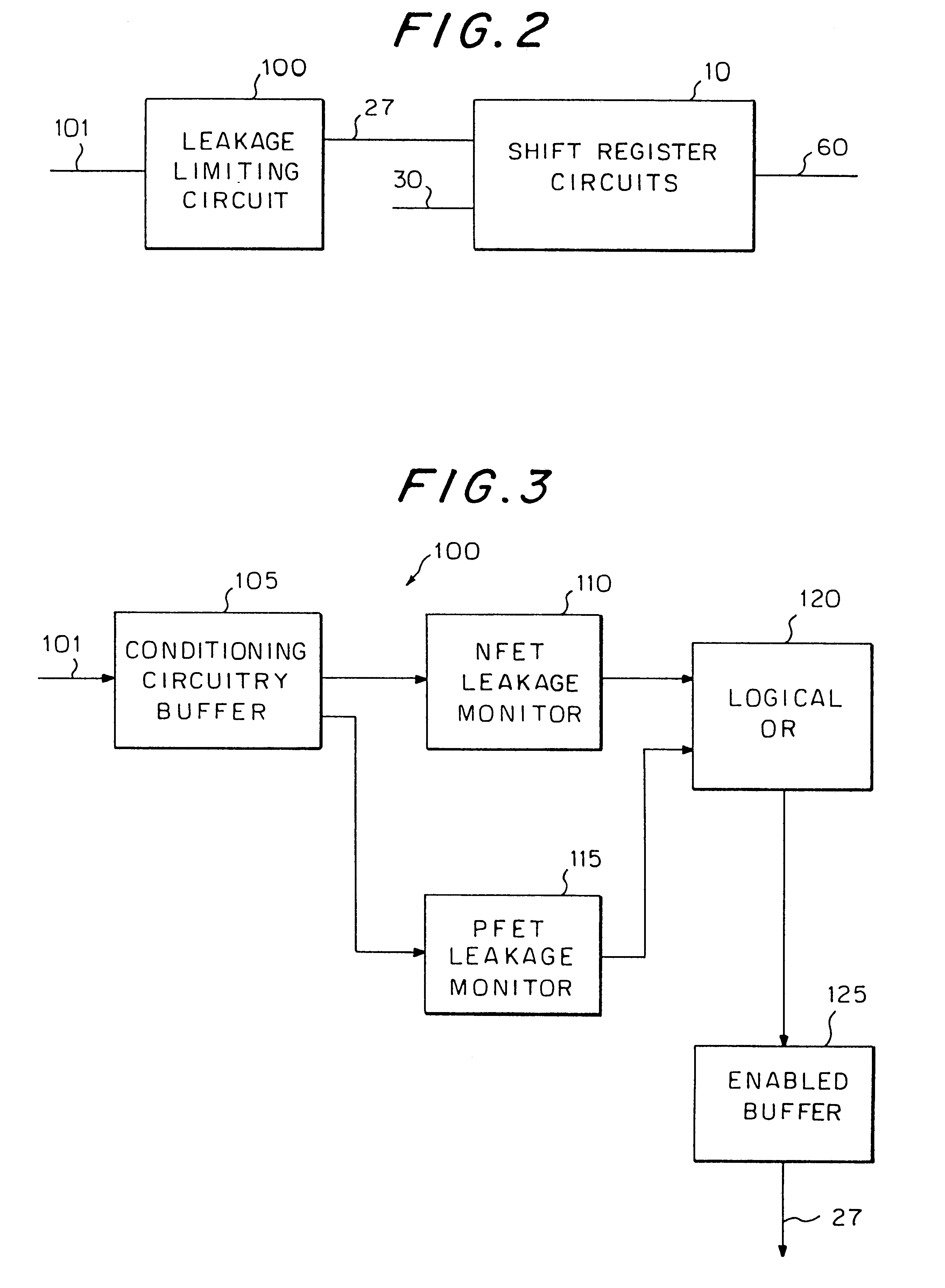
FIG. 2 illustrates an embodiment of the present invention in the context of surrounding circuits. In particular, FIG. 2 illustrates a leakage limiting circuit 100 connected to the shift register circuit 10. An input to the leakage limiting circuit 100 is an input shift signal 101. The output of the leakage limiting circuit 100 is the shift signal 27, which is an input to the shift register circuit 10. Broadly speaking, the leakage limiting circuit 100 processes the input shift signal 101 such that shift pulses propagating through to the shift signal 27 have a duration that is controlled, limited, abbreviated, truncated or shortened, so as to avoid subthreshold leakage in the shift register circuit 10. One skilled in the art will readily recognize that the shift register circuit 10 is exemplary of a broad class of circuits to which the leakage limiting circuit 100 can be put to good use. For example, any circuit having one or more dynamic storage nodes or pass gates would benefit fro...


PUM


Abstract

Disclosed are circuits and methods that prevent failure modes in related circuits. The circuit processes a pulse for use with a related circuit. The circuit comprises a timer and one or more logic gates. The timer produces an output in a given state if the duration of the pulse reaches a predetermined amount of time. The predetermined amount of time is related to a parameter of the related circuit. The one or more logic gates have an output that is the same as the pulse unless and until the output of the timer is in the given state, at which time, the output of the one or more logic gates is forced to a non-pulsed state. Preferably, the parameter is a subthreshold leakage rate across an FET. The method is used with a circuit in which leakage can occur at a first rate. The method comprises the step of sensing a condition that prompts leakage to occur in the circuit. In response to the sensing step, the method produces a related leakage at a faster rate than the first rate. The method disables the condition if the related leakage reaches a predetermined level. Preferably, the condition is a pulse.

Description

The invention relates to digital pulse generators. More particularly, the invention relates to methods and apparatus for tracking subthreshold leakage during an active period and generating digital pulses to avoid deleterious effects of subthreshold leakage.In certain applications, it is desirable to limit the amount of time a signal is active in CMOS (complementary metal oxide semiconductor) circuits to protect the circuits against various circuit failure modes. One example of a circuit failure mode is a dynamic decay due to subthreshold leakage. A shift register circuit 10 is shown in FIG. 1 for the purpose of illustrating the deleterious effects of subthreshold leakage. The shift register circuit 10 is shown with only three stages for ease of understanding. Each stage comprises a pass gate 15, a dynamic storage node 35, 45 or 55 and an inverter formed by a PFET (P-channel field effect transistor) 20 and an NFET (N-channel field effect transistor) 25. A shift signal 27 and its inv...

Claims


Application Information

Patent Timeline
Patent Type & Authority Patents(United States)
IPC IPC(8): H03K19/003G11C19/00H03K5/1252
CPCG11C19/00H03K19/00384H03K19/00361H03K5/1252
Inventor NAFFZIGER, SAMUEL D
Owner HEWLETT PACKARD DEV CO LP
Why Eureka
Try Eureka