It uses costly repeaters.
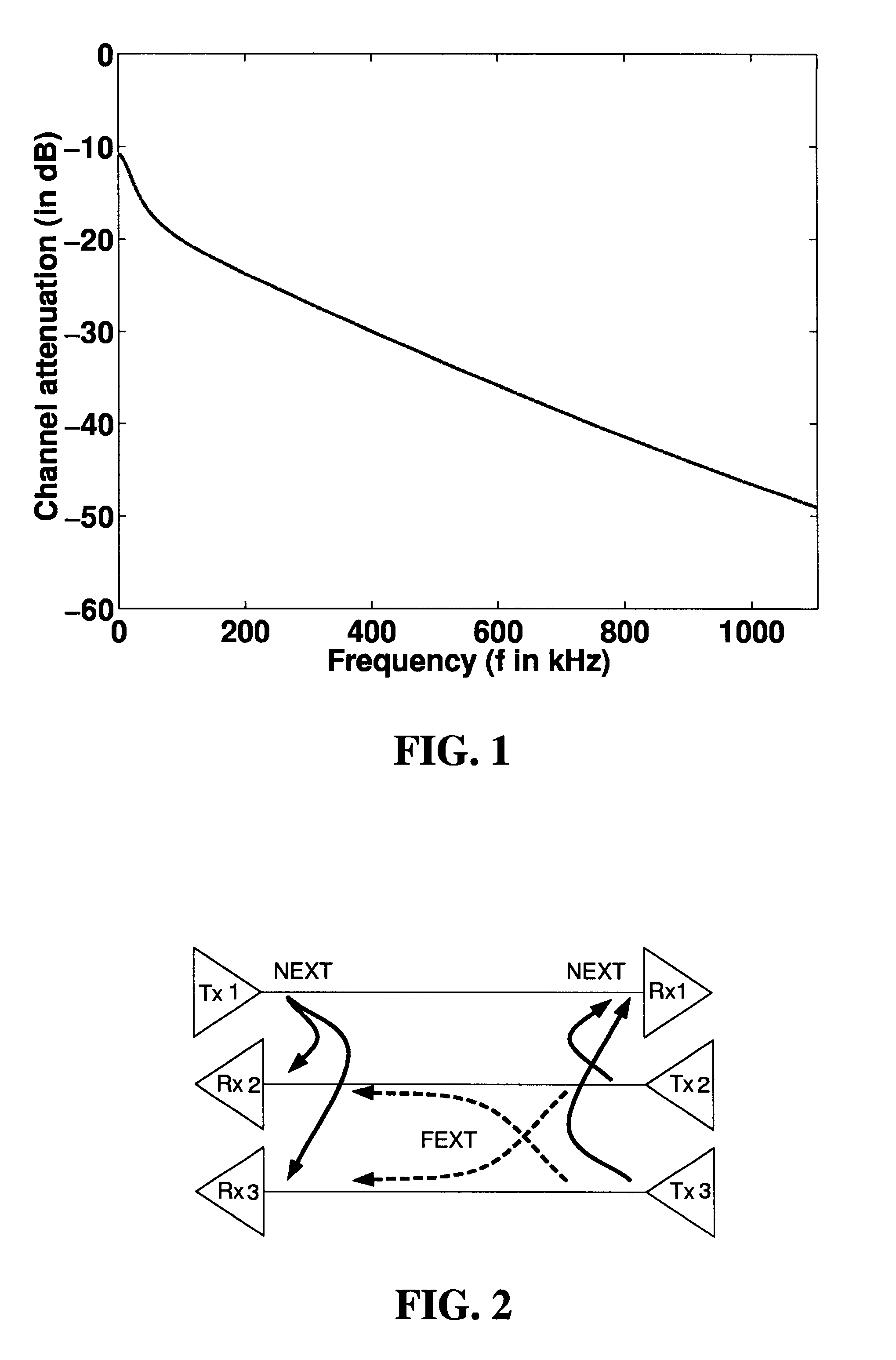
Due to the close proximity of the lines within a binder, there is considerable amount of
crosstalk interference between different neighboring telephone lines.
However, due to the proximity of the lines in a cable, there is considerable DSINNEXT, DSIN-FEXT, self-NEXT and self-FEXT interference from T1, ISDN, HDSL, ADSL and HDSL2 into HDSL2 --this interference reduces the capacity of the HDSL2 service.
This problem is known as spectral compatibility.
No prior
system has been developed that systematically optimizes the HDSL2 spectrum and reduces interference effects both from and into HDSL2.
Further, a modulation scheme for HDSL2 has not been decided upon at this time.
Further, in CDS each service occupies the entire available bandwidth for all of the time.
The scheme in [3] is optimized, but only for an over simplified
scenario (and therefore not useful in practice).
In particular, [3] does not address self-FEXT and interference from other lines as considered in this work.
Further, [3] does not address spectral compatibility issue.
Note, however, that multitone modulation is definitely not the only modulation scheme that can be used to implement (optimal) transmit spectra.
However, these schemes by no means optimize the capacity of the services considered.
The development of [3] does not address
crosstalk from other sources, such as DSIN-NEXT and DSIN-FEXT, or self-FEXT, or other types of additive
Gaussian noise.
The development of [3] also does not address spectral compatibility of the designed service with respect to other services.
The interference characteristics may include an amount of
self interference into the communications channel from the other communications channels that carry the same
type of service.
The interference characteristics may also include an amount of uncorrelated interference.
Some of the uncorrelated interference may be cross talk from other communications channels that carry a different
type of service.
The interference may take the form of similar services being transmitted on neighboring transmission mediums and / or may take the form of uncorrelated interference from different services on neighboring transmission mediums and or interference from various
noise sources which affect the
transmission medium.
Due to the close proximity of the transmission mediums comprised in a subscriber cable, a given subscriber line is subject to interference from neighboring transmission mediums, including self-NEXT and self-FEXT interference, and different service interference (DSIN).
If one or more of the other communications channels carry a different
type of service than the service on the communications channel, then the uncorrelated interference may include different-service interference (DSIN) from the other communications channels carrying the different service.
This
scenario makes the power distribution problem more difficult however (see Section 4.10).
This type of orthogonal signaling completely eliminates self-NEXT but does not combat self-FEXT.
In frequency bins where self-FEXT is high, using FDS is not sufficient since self-FEXT still exists.
Recall the FDS signaling tradeoff: FDS eliminates self-NEXT and therefore increases
system capacity; however, FDS also reduces the bandwidth available to each
transmitter /
receiver pair and therefore decreases system capacity.
Unfortunately, this would reduce the bandwidth available to each transmitter to 1 / M the overall channel bandwidth In a typical implementation of HDSL2, M will lie between 1 and 49; hence orthogonal signaling (multi-line FDS) for eliminating self-FEXT is worth the decrease in capacity only when self-FEXT is very high.
However, in low self-NEXT regions, the loss of
transmission bandwidth of FDS may outweigh any
gain in capacity due to self-NEXT rejection.
However, this gives low capacities.
Lines carrying the same xDSL service and different xDSL services interfere with the line under consideration.
Such a transmit spectrum is easily implemented via a DMT modulation scheme, but is not easy to implement with other modulation schemes like PAM, multi-level PAM, or
QAM [20].
In addition, the DMT scheme can introduce high latency which may be a problem in some applications.
In the case of a peak power constraint in frequency, we may not be able to use a power-peaky scheme like FDS in some spectral regions.
This may not necessarily yield the optimal solution for the transmit spectrum given that we use a joint signaling scheme comprising of the three signaling schemes (EQPSD, FDS and multi-line FDS).
Often in practice we may have only two
twisted pair lines carrying the same service and interfering with each other.
and the positivity and new peak power constraints
On the other hand, OPTIS transmit spectra have a large spectral overlap at lower frequencies (self-NEXT is high here) that significantly reduces its performance margins (see Table 7).
The "1 dB below OPTIS" transmit spectra do not do this, and so have inferior performance.
Further, comparing these results with those in Table 1 suggests that the OPTIS PSD
mask is not a good constraining PSD
mask, since the unconstrained in peak power margins in Table 1 are significantly higher than the ones in Table 7.
These reflections destructively interfere with the transmitted
signal over certain frequencies.
Thus, bridged taps
pose an important problem in achieving high bit rates over xDSL lines..sup.9
.sup.9 Bridged taps can be removed from xDSL lines, but this is an expensive (labor-intensive) procedure.
Optimal signaling is more computationally expensive to implement in the presence of bridged taps [3], as the channel
transfer function has nulls and thus loses its monotonicity.
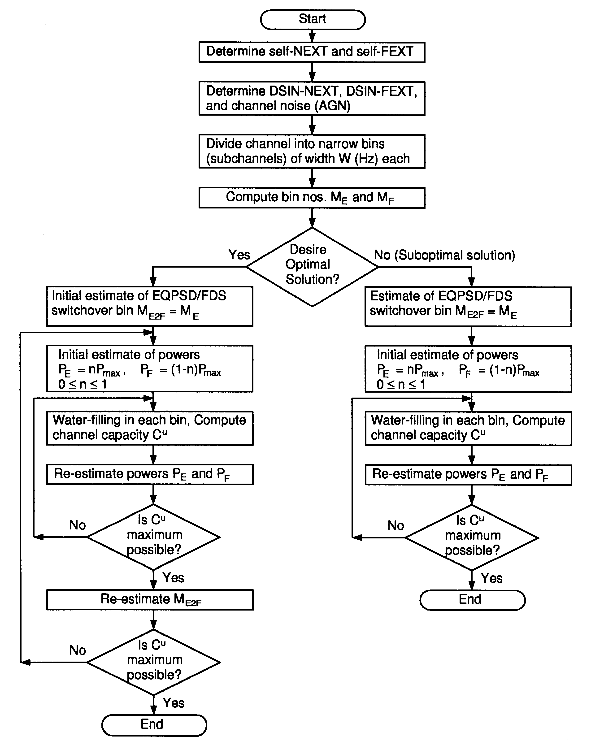
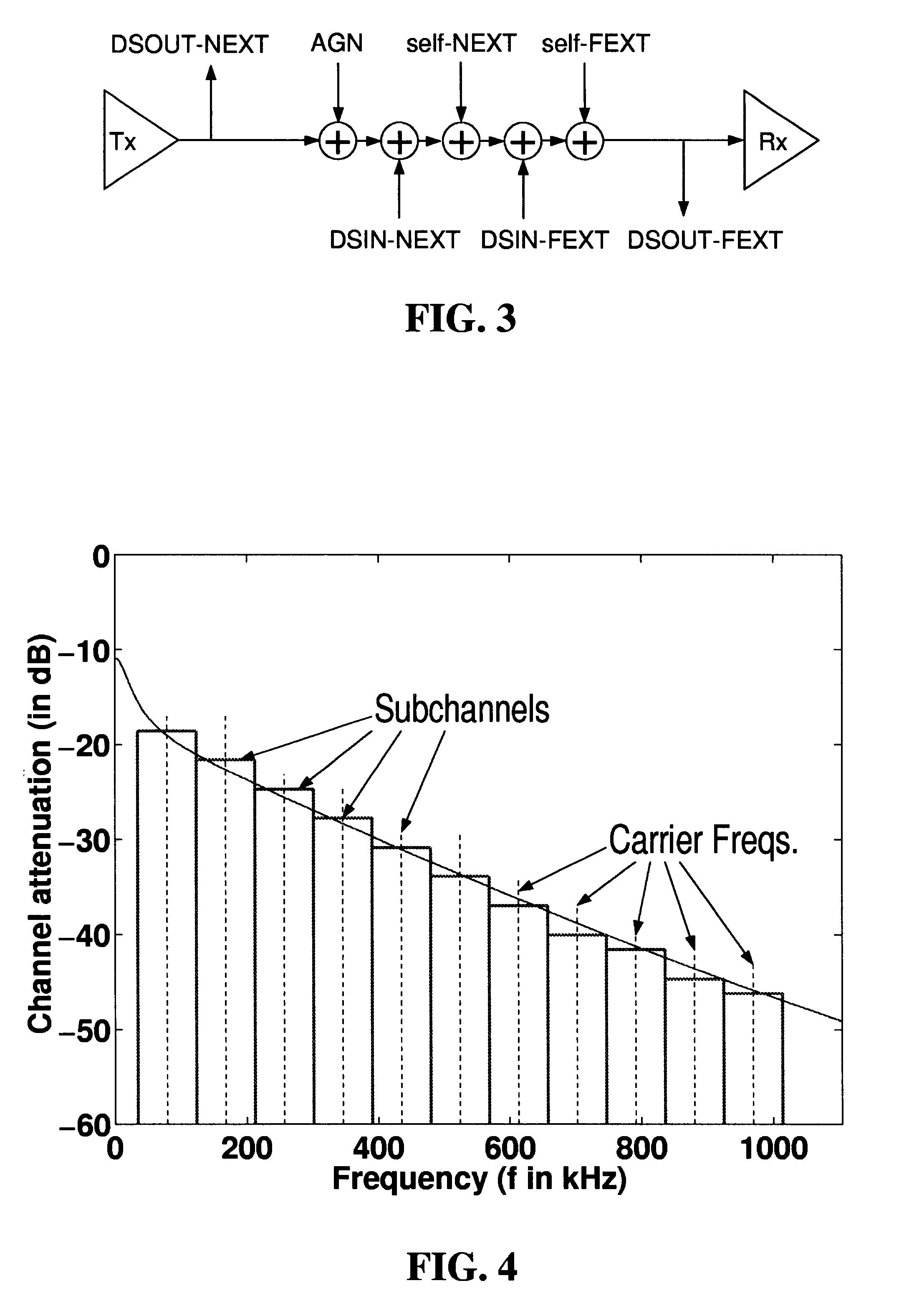
1. Divide the
frequency axis into narrow bins or subchannels. Compute channel transfer function, various interference transfer functions, and AGN.
2. Choose an initial power distribution of P.sub.max over all bins.
3. Given the powers in each bin decide the optimal signaling scheme in each bin. Compute capacities for each bin and hence compute
channel capacity.
4. Re-distribute the powers in each bin by water-filling [14], [16], decide the optimal signaling scheme in each bin, and re-calculate the
channel capacity. Repeat this step until we find the maximum possible channel capacity. It can be exceedingly computationally intensive to find the optimal power distribution over all bins. There can be several local maxima for the channel capacity curve, and there is no guarantee that
a search algorithm will converge to the global maximum.
The search for the optimal switchover bins from one signaling scheme to the other could be exceedingly expensive (involving a multi-dimensional search).
We saw in the previous Section that the optimal transmit spectrum could be very expensive to obtain.
In such a
scenario, the optimal power distribution
algorithm of Section 4.10.1 is exceedingly difficult to implement.
All these
broadband modulation schemes do not suffer from latency as DMT does, but the DFE structure is complex.
In this case a power-peaky signaling scheme like FDS or multi-line FDS will no longer be optimal as now we have a peak power constraint instead of the average power constraint.
Note that implementation of SS-CDS cannot give perfectly orthogonal codes; instead we have only codes with very low cross-correlation.
We have seen that self-interference is a major
limiter in achieving higher channel capacity.


