
Binder identification

a technology of binding and identification, applied in the field of binding identification, can solve the problems of high crosstalk noise and limited performance of dsl systems

Inactive Publication Date: 2011-12-06
ASSIA SPE LLC CO THE CORP TRUST CO
View PDF60 Cites 15 Cited by
  • Summary
  • Abstract
  • Description
  • Claims
  • Application Information

AI Technical Summary

Benefits of technology

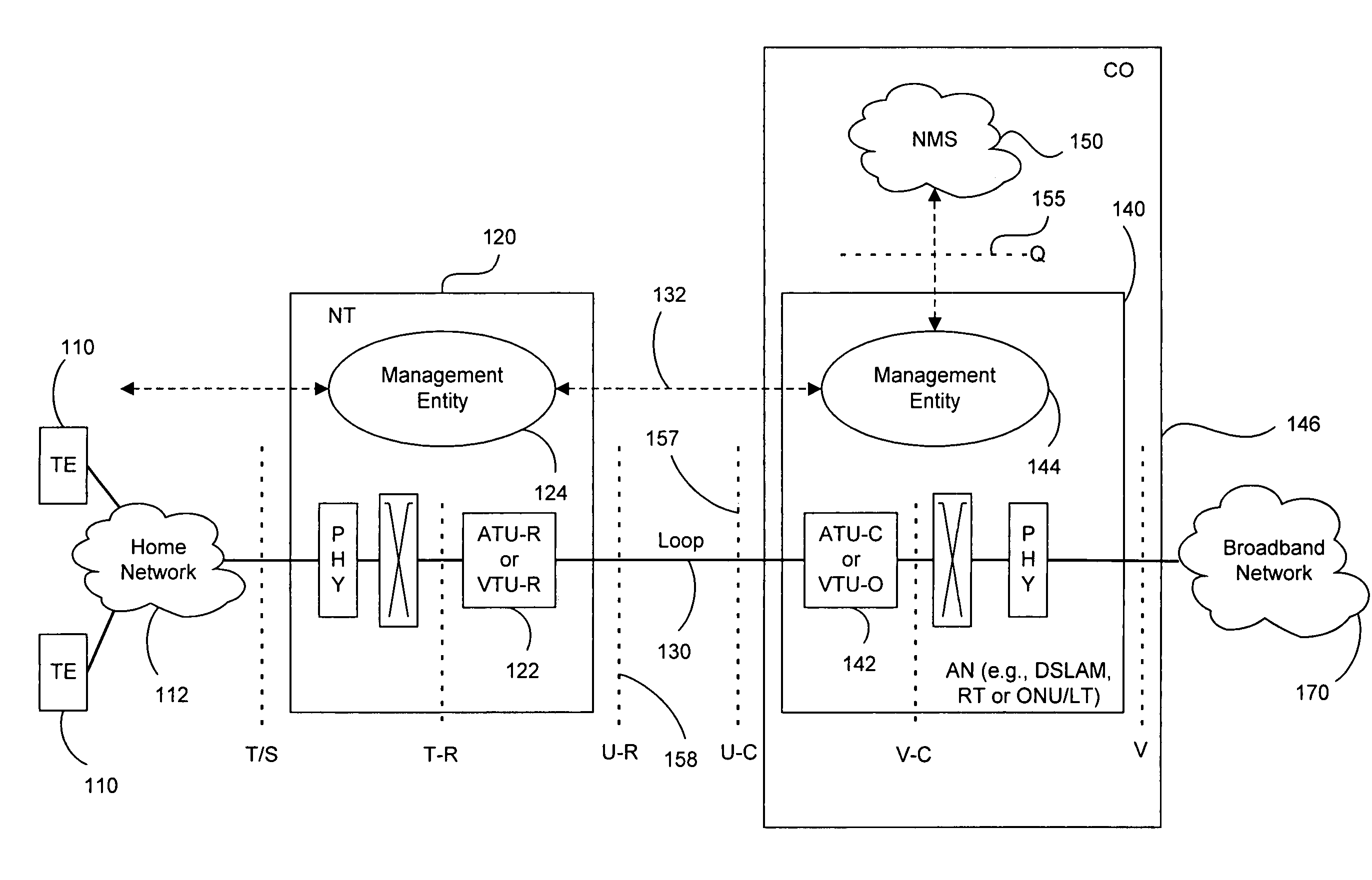
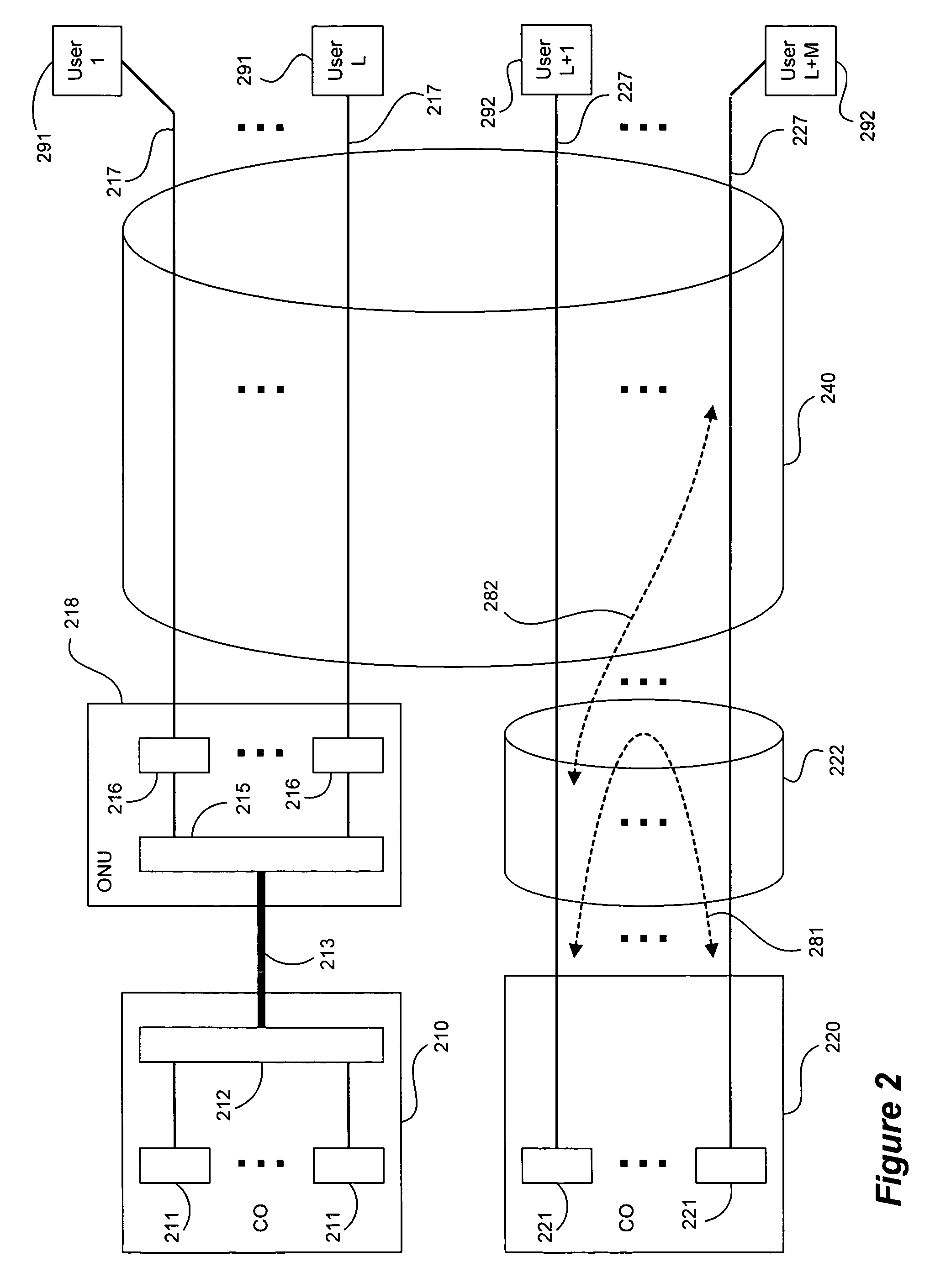
"The present invention provides methods, techniques, and apparatus for identifying members and characteristics of groups of DSL lines. This can help in DSL systems where multiple telephone lines create crosstalk that can become dominant impairments to other lines. The invention can identify significant crosstalking \"offenders\" and their affected \"victims\" by collecting operational data in connection with use of one or more line profiles. The invention can also design transmit spectra to reduce crosstalk interference and identify absolute values of crosstalk channels making up a channel transfer function. Overall, the invention can help improve the performance and reliability of DSL systems."

Problems solved by technology

The performance of DSL systems is very often limited by the effects of crosstalk noise at the DSL receivers.
Crosstalk noise is particularly strong when twisted pairs are physically close, such as when they share a common binder.

Method used


Image

  • Binder identification
  • Binder identification
  • Binder identification

Examples


example 1

[0065]Given that 3-4 sources (“offenders”) usually dominate crosstalk noise of a “victim” pair, it is not beneficial to continue crosstalk identification for those pairs for which 3-4 “offenders” have already been identified.

example 2

[0066]If the crosstalk channel from “offender” A to “victim” B has been identified, then the crosstalk channel from “offender” B to “victim” A is likely to be very similar.

[0067]Binder identification requires a victim line to perform noise measurements, which can then be used to estimate crosstalk from other lines. The accuracy of such measurements can be enhanced by setting the programmable-gain-amplifiers (PGA) of the receiver to the highest settings possible. This ensures that the external crosstalk noise is strong relative to internal receiver noise sources. Given that the PGA gains are usually chosen using algorithms that are implemented inside the modem, an indirect method to affect the PGA gains can include controlling the transmitted signal power. Thus, it is beneficial for the transmitted signal power at the victim line transmitter to be set low during noise measurements, so that the crosstalk can be identified with higher accuracy (that is, so that crosstalk is larger rela...


PUM


Abstract

Methods, techniques and apparatus identify members and characteristics of binders and / or other groups of communication lines such as those in a DSL system. Information obtained includes the identification (for example, by scanning) of significant crosstalking “offenders” and their “victims” that are affected by the crosstalk. One or a small number of modems are instructed to transmit with preselected transmit spectra, after which evidence of crosstalk in the noise spectrum data is examined for potential victim lines. Direct evidence of noise spectrum contribution by a suspected offender line may be obtained by collecting reported noise spectrum data and / or estimated noise spectrum data from potential victim lines. Also, where such direct evidence is not available, or in addition to it, other operational data showing crosstalk interference relating to potential victim lines can be used. The transmitting modem can either be on the CO / RT side or on the CPE side. Modems other than suspected offenders might transmit zero or minimal power in one or more selected frequency bands during scanning to reduce the risk that a modem and / or line not being examined for “offender” status supplies unnecessarily complicating and / or dominant crosstalk during the procedure. For DMT modulated DSL transceivers, well designed transmit spectra can be easily enforced by manipulating line profiles where such well designed line profiles cause minimal or no interruption to existing DSL customers. The invention also can be used to identify (partially or fully) the absolute values of crosstalk channels making up a channel transfer function.

Description

CROSS-REFERENCE TO RELATED APPLICATIONS[0001]This application claims the benefit of priority under 35 U.S.C. §119(e) of the following:[0002]U.S. Provisional No. 60 / 679,508 filed on May 10, 2005, entitled BINDER IDENTIFICATION, the entire disclosure of which is incorporated herein by reference in its entirety for all purposes.[0003]U.S. Provisional No. 60 / 698,113 filed on Jul. 10, 2005, entitled DSL SYSTEM, the entire disclosure of which is incorporated herein by reference in its entirety for all purposes.STATEMENT REGARDING FEDERALLY SPONSORED RESEARCH OR DEVELOPMENT[0004]Not applicable.REFERENCE TO SEQUENCE LISTING, A TABLE, OR A COMPUTER PROGRAM LISTING COMPACT DISK APPENDIX[0005]Not applicable.BACKGROUND[0006]1. Technical Field[0007]This invention relates generally to methods, systems and apparatus for managing digital communications systems.[0008]2. Description of Related Art[0009]Digital subscriber line (DSL) technologies provide potentially large bandwidth for digital communic...

Claims


Application Information

Patent Timeline
Patent Type & Authority Patents(United States)
IPC IPC(8): H04M9/00
CPCH04M3/304H04B3/487H04M11/062
Inventor RHEE, WONJONGLEE, BINALMANDOZ, IKERCIOFFI, JOHN M.GINIS, GEORGIOS
Owner ASSIA SPE LLC CO THE CORP TRUST CO
Learn More