Drying end of a machine for the production of a material web and method of drying a material web

a technology of drying end and material web, which is applied in the direction of pulp material addition process, paper after-treatment, washing apparatus, etc., can solve the problems of excessive stretching of the edges of the web, web breakage, and more pronounced problems at higher web speeds

Inactive Publication Date: 2001-09-25
VOITH PATENT GMBH
View PDF37 Cites 15 Cited by
  • Summary
  • Abstract
  • Description
  • Claims
  • Application Information

AI Technical Summary

Problems solved by technology

At the beginning of the drying process, when the paper web still does not have adequate strength, problems frequently occur with regard to web guidance which are often attributed to the fact that the still-moist web continues to adhere to the smooth contact surfaces of the drying end, the smooth surfaces being necessary for adequate heat transfer.
This adhesion often results in breakage of the web as well as excessive stretching of the edges of the we

Method used


Image

  • Drying end of a machine for the production of a material web and method of drying a material web
  • Drying end of a machine for the production of a material web and method of drying a material web
  • Drying end of a machine for the production of a material web and method of drying a material web

Examples


first embodiment

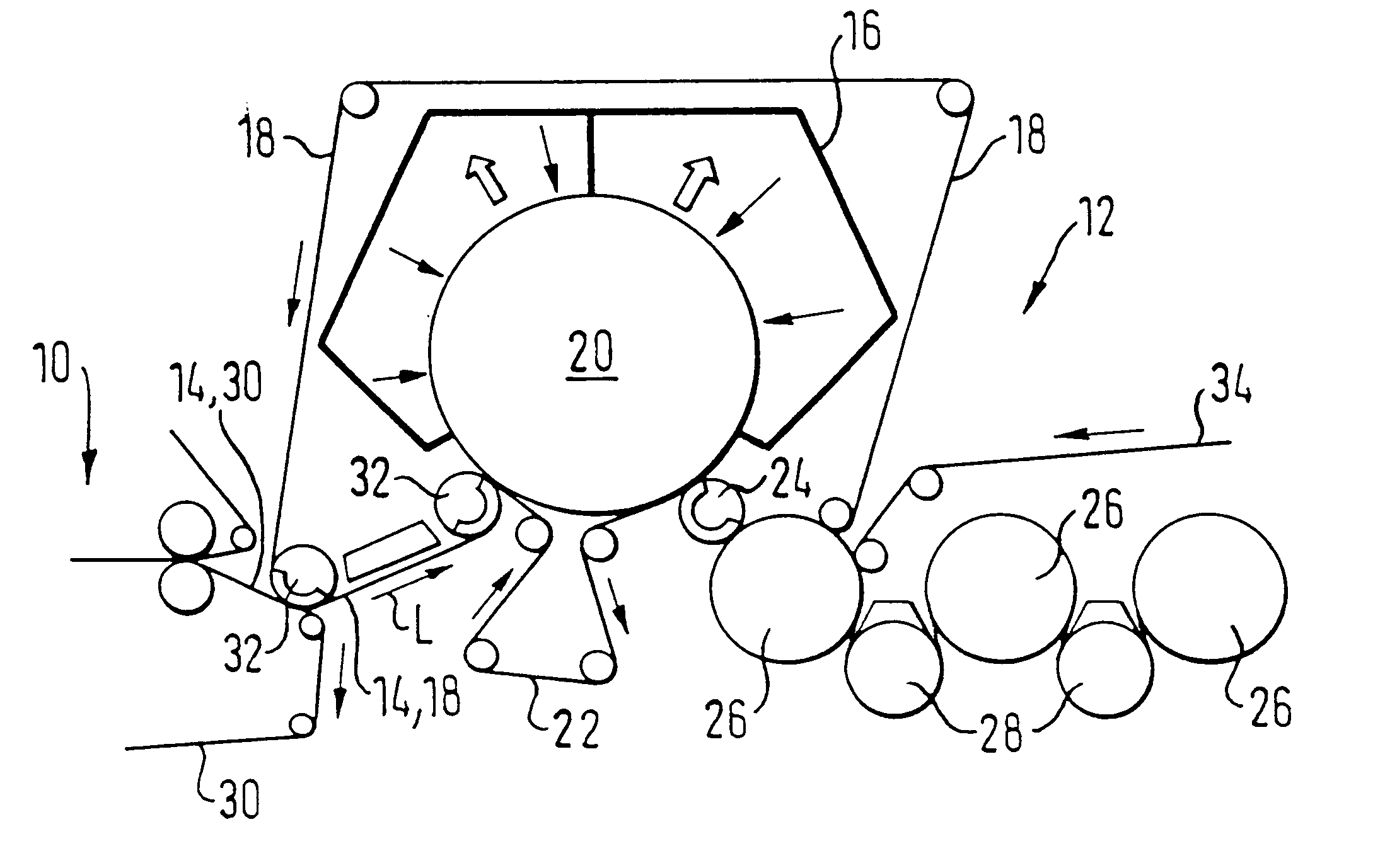
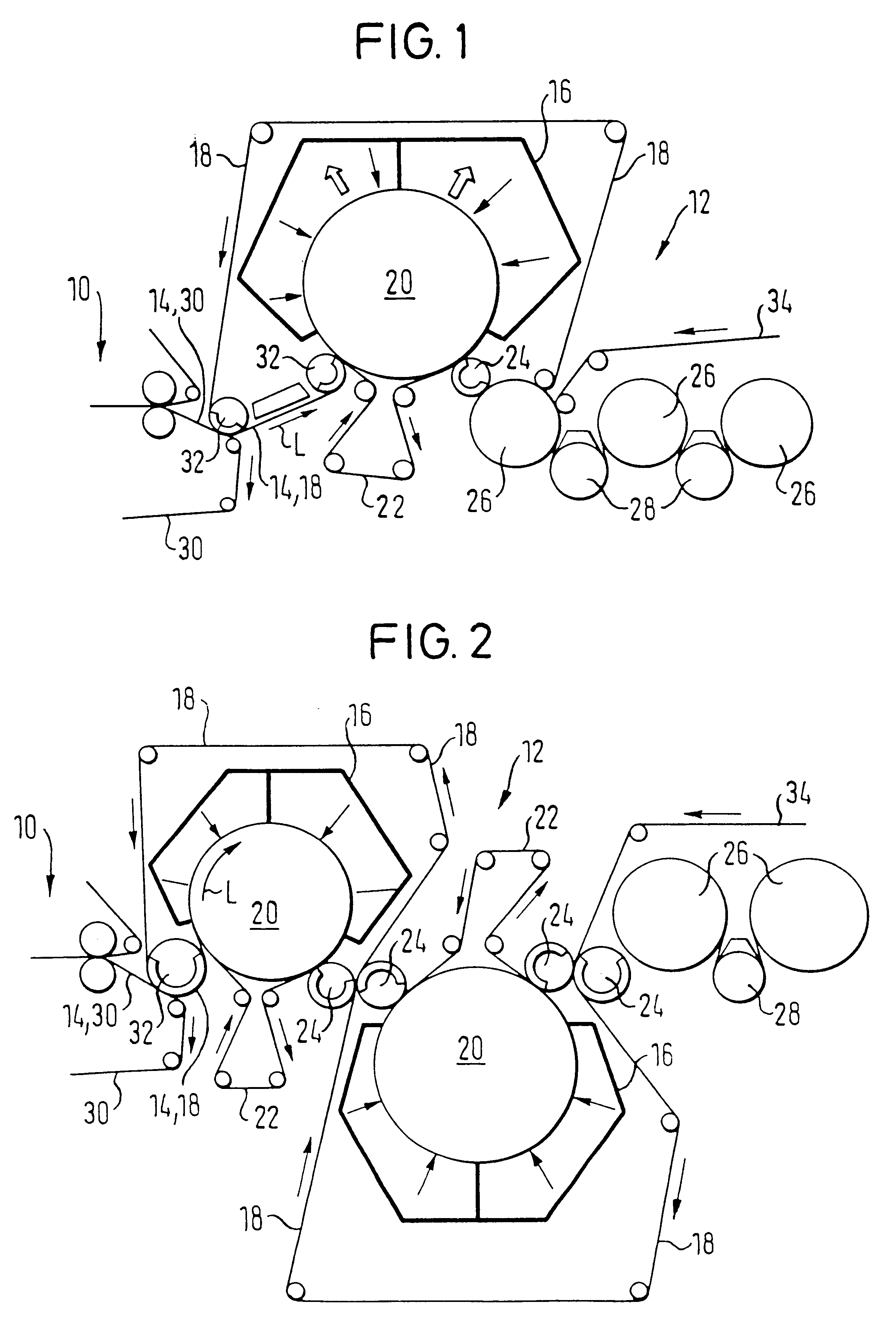
In a first embodiment shown in FIG. 1, the drying end 12 includes an impact flow drier 16 positioned above the material web (the drier is positioned about an upper portion of the circumference of a large support roll 20), whereupon the material web 14 is bombarded with a hot air and / or hot steam impact flow on one surface of the material web. The material web 14 is guided with its surface opposite the impact flow drier 16 (i.e, the bottom surface) over an open (i.e., not smooth), support surface. The material web 14 is guided along with a cover wire 18 over the large support roll 20 by a bottom wire 22 on the opposite web surface (i.e, the bottom surface). In the present embodiment, the bottom wire 22 forms the open support surface. Subsequent removal of the material web 14 and the cover wire 18 is facilitated by this continuous bottom wire 22.

In a removal zone downstream from the large support roll 20, the material web 14 is guided, along with the cover wire 18, around a suction ro...
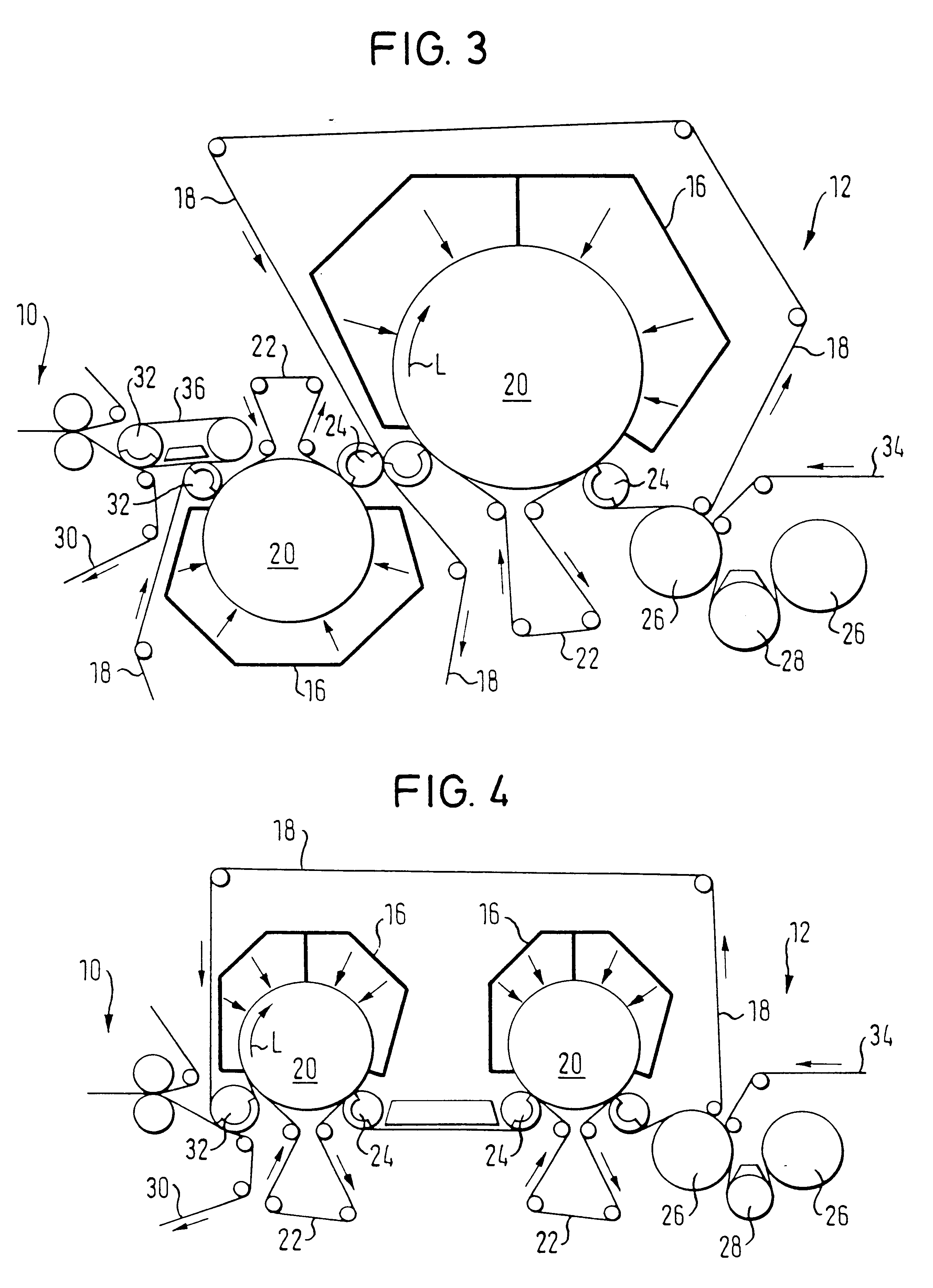
fourth embodiment

FIG. 4 shows a drying end 14, with two upper impact flow driers 16, each associated with one large bottom support roll 20, which driers bombard the material web 14 on the same web surface. As shown in FIG. 4, a common cover wire 18 is guided over the two bottom support rolls 20. Each of the two support rolls 20 are partially surrounded by a respective bottom wire 22 that has an open support surface.

fifth embodiment

FIG. 5 shows a drying end 14, in which the material web 14 is guided between the cover wire 18 and the bottom wire 22 over a plurality of support rolls 38 arranged in an arc. The open support surface facilitating the pickup of the material web 14 and cover wire 18 is formed by the bottom wire 22. The material web 14 is thus passed between the two wires 18, 22 to the impact flow drier 16 arranged above the web.

The bottom wire 22 may also be eliminated. Instead, the open support surface can be formed by the surface or a covering or coating of the support roll 20. For example, a shrink wire or the like can be applied to the support roll 20, or the relevant support roll 20 can be provided with a coated surface. The support roll 20 may, for example, have a solid sleeve or spoke / lattice design or even be a polygon.

As shown in FIG. 5, the web may be supported by a plurality of small support rolls 38 which are arranged in an arc such that the radius of curvature of the material web 14 is vi...


PUM

PropertyMeasurementUnit
Fractionaaaaaaaaaa
Fractionaaaaaaaaaa
Angleaaaaaaaaaa

Abstract

Drying end of a machine for the production of a material web such as paper or cardboard. The drying end includes at least one impact flow drier configured to bombard at least one surface of the material web with hot air or hot steam impact flow. Also provided is a method for drying a material web including bombarding the material web on at least one surface with hot air or hot steam impact flow, via at least one impact flow drier.

Description

The present application claims priority under 35 U.S.C. .sctn.119 of German Patent Application No. 198 41 768.3, filed on Sep. 11, 1998, the disclosure of which is expressly incorporated by reference herein in its entirety.1. Field of the InventionThe invention relates to a method for drying a material web and to a drying end of a machine for the production of a material web, and in particular, a paper or cardboard web.2. Discussion of Background InformationDuring drying, in a known multi-cylinder drying end, a paper web is guided over a plurality of steam-heated cylinders and often also over suction rolls. At the beginning of the drying process, when the paper web still does not have adequate strength, problems frequently occur with regard to web guidance which are often attributed to the fact that the still-moist web continues to adhere to the smooth contact surfaces of the drying end, the smooth surfaces being necessary for adequate heat transfer. This adhesion often results in b...

Claims


Application Information

Patent Timeline
IPC IPC(8): D21F5/00D21F5/18
CPCD21F5/00D21F5/182D21F5/18
Inventor OECHSLE, MARKUSCHAU-HUU, TRIMAYER, ROLAND
Owner VOITH PATENT GMBH
Why Eureka
Try Eureka