Accessory mounting structure for internal combustion engine

a technology for mounting structures and internal combustion engines, which is applied in the direction of machines/engines, machine supports, transportation and packaging, etc., can solve the problem of increasing the overall length of the internal combustion engine further

Inactive Publication Date: 2006-03-14
HONDA MOTOR CO LTD
View PDF7 Cites 9 Cited by
  • Summary
  • Abstract
  • Description
  • Claims
  • Application Information

AI Technical Summary

Benefits of technology

[0007]The present invention has been made in view of the foregoing problems and it is therefore an object of the present invention to provide an accessory mounting structure for an internal combustion engine having an engine body and an accessory bracket holding accessories and attached to the engine body, capable of making the internal combustion engine to be formed in the shortest possible overall length.
[0011]The accessory support part reinforced with the reinforcing rib enables forming the internal combustion engine to be formed in a short overall length, is capable of stably holding the accessory, and increases the rigidity of the accessory bracket.
[0013]Because at least one of the attaching parts to be fastened to the engine body to attach the accessory bracket to the engine body, and the accessory support part are connected by the reinforcing rib, the vibration of the accessory bracket caused by the vibration of the internal combustion engine can be suppressed, the accessory can be further stably held, fastening strength fastening the accessory bracket to the engine body can be enhanced.
[0015]Because the automatic tensioning device is held on the accessory bracket partly sunk in the engine body and rigidly fastened to the engine body, the automatic tensioning device continuously subjected to a reaction force can be firmly held, belts for driving the accessory can be disposed close to the engine body, and hence the internal combustion engine have a in compact construction.

Problems solved by technology

On the other hand, the thickness of the oil pump body must be increased to form a rigid accessory mounting seat, which further increases the overall length of the internal combustion engine.

Method used


Image

  • Accessory mounting structure for internal combustion engine
  • Accessory mounting structure for internal combustion engine
  • Accessory mounting structure for internal combustion engine

Examples


Embodiment Construction

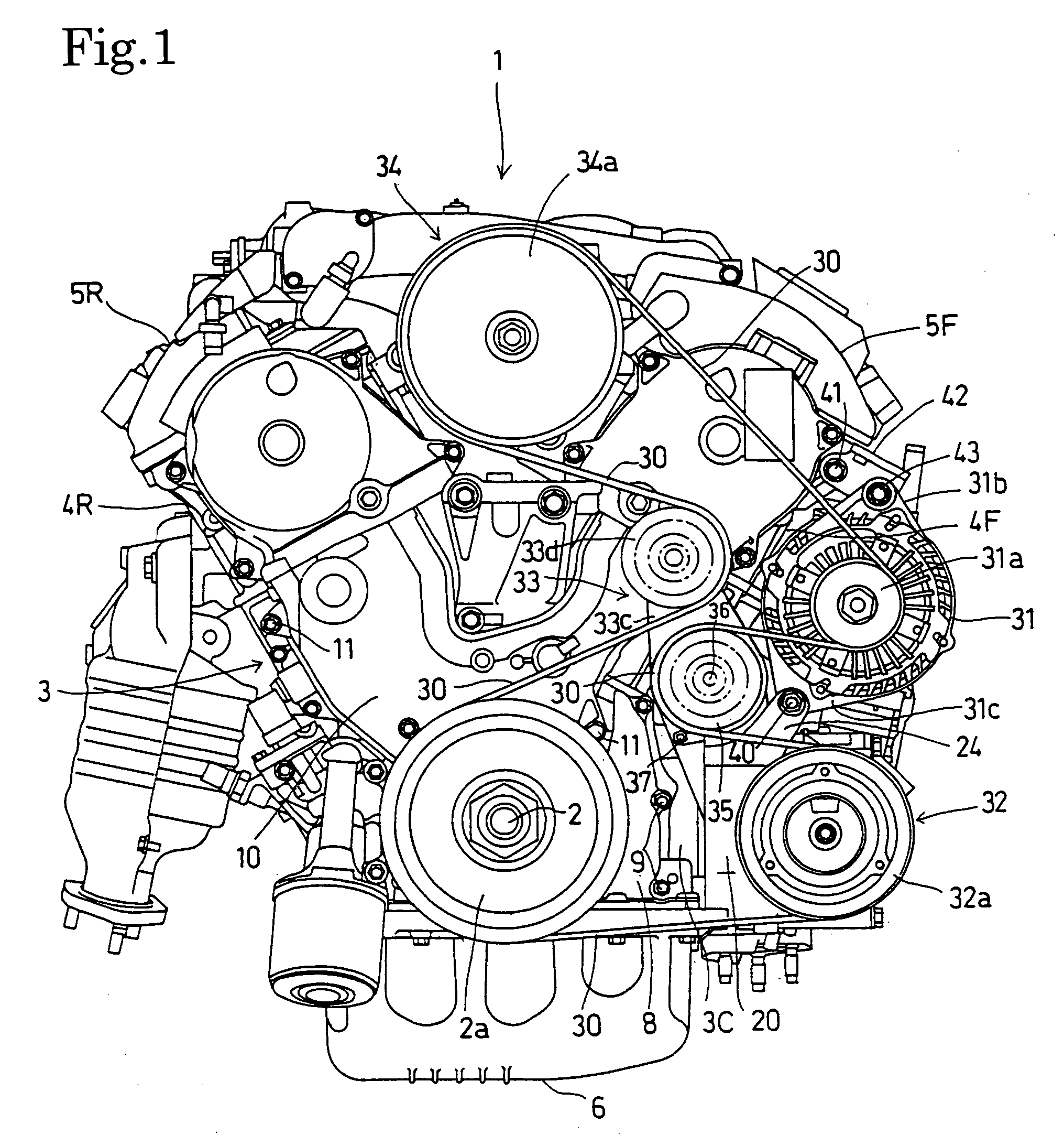
[0030]Referring to FIG. 1 showing an internal combustion engine 1 including an accessory mounting structure in a preferred embodiment according to the present invention, the internal combustion engine is a four-stroke-cycle V-6 internal combustion engine provided with two cylinder banks of three cylinders each, namely, a front cylinder bank 3F and a rear cylinder bank 3R, set at an angle. The internal combustion engine 1 is mounted laterally on the body of a vehicle with its crankshaft 2 extended laterally in a horizontal position, the three cylinders of the front cylinder bank 3F tilted forward and the three cylinders of the rear cylinder bank 3R tilted rearward.

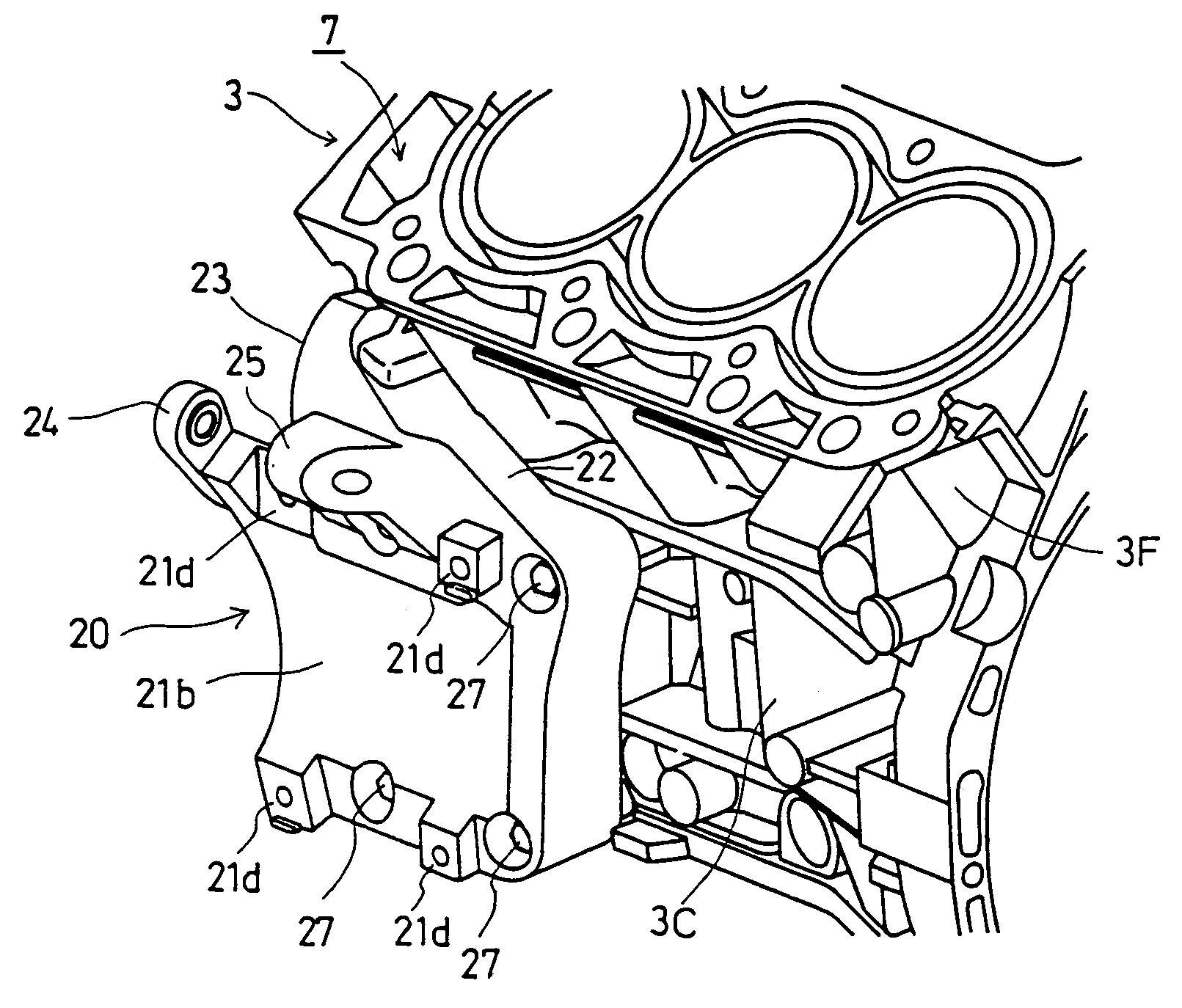
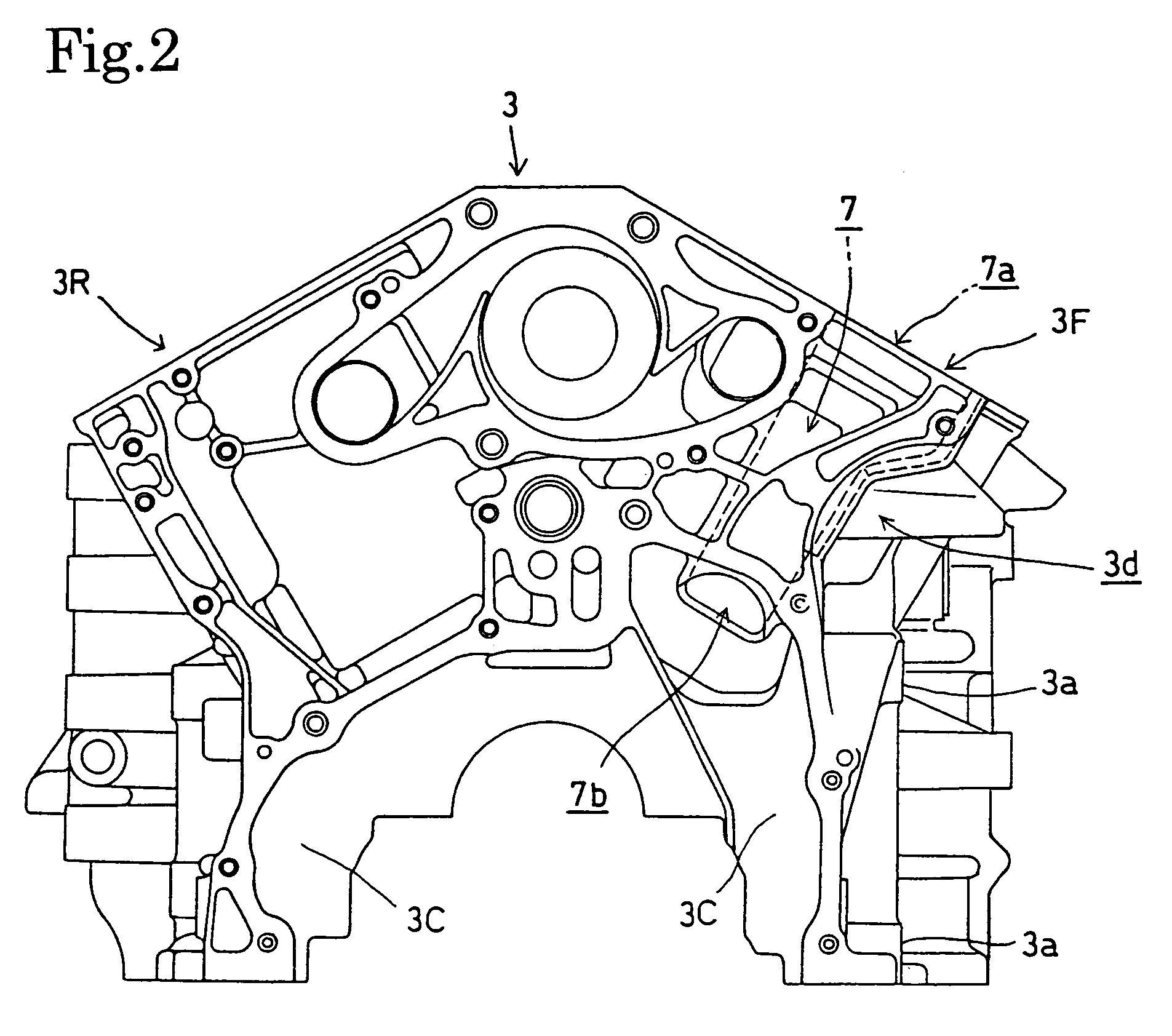
[0031]As shown in FIGS. 2 and 3, the front cylinder bank 3F and the rear cylinder bank 3R are set at an angle in the shape of the letter V, and a crankcase 3C is formed under the middle joining part joining the front cylinder bank 3F and the rear cylinder bank 3R. The front cylinder bank 3F and the rear cylinder bank 3R are...


PUM


Abstract

An accessory mounting structure has an accessory bracket holding accessories thereon and attached to the engine body of an internal combustion engine, to provide a shortest possible overall length. The accessory mounting structure includes an end part, with respect to a direction parallel to a crankshaft, of the engine body, provided with a passage, a part of the engine body, provided with a recess extending along the passage, and the accessory bracket partly sunk in the recess and fastened to the engine body. At least one accessory, such as an automatic tensioning device is held on the accessory bracket.

Description

BACKGROUND OF THE INVENTION[0001]1. Field of the Invention[0002]The present invention relates to an accessory mounting structure for an internal combustion engine, such as an automotive internal combustion engine.[0003]2. Description of the Related Art[0004]In an internal combustion engine disclosed in JP-A No. 193473 / 2001 provided with accessories arranged on one side of an engine body along a crankshaft, an oil pump body is attached to a side surface of the engine body, an accessory bracket is attached to the oil pump body, and accessories are held on the accessory bracket.[0005]Because the accessory bracket is attached to the oil pump body which in turn is attached to the engine body, the overall length of the internal combustion engine increases by a length corresponding to the width of the oil pump body.[0006]On the other hand, the thickness of the oil pump body must be increased to form a rigid accessory mounting seat, which further increases the overall length of the internal...

Claims


Application Information

Patent Timeline
Patent Type & Authority Patents(United States)
IPC IPC(8): F02F7/00B60K25/06F02B67/00F02B67/04F02B67/06F02B75/18
CPCF02B67/00F02F7/0073F02F7/0012F02B2075/1824
Inventor YAMAGATA, TAKAYUKIKOYAMA, YOSHIAKI
Owner HONDA MOTOR CO LTD
Why Eureka
Try Eureka