Device for controlling a relative rotation between two articulated elements and a deployable mechanical structure, particularly for a space vehicle, using at least one device of this type

Inactive Publication Date: 2001-10-09
ALCATEL LUCENT SAS
View PDF6 Cites 24 Cited by
  • Summary
  • Abstract
  • Description
  • Claims
  • Application Information

AI Technical Summary

Problems solved by technology

When a spring folding mechanism is used, substantial jarring occurs at the end of deployment, which may damage or disturb the mechanism of the equipment stowed on the space vehicle.
However, this reduces the reliability of the mechanism.
When an electric motor is used to control deployment, there are fitting constraints associated with the space requirement of the motor.
Moreover, the unit constituted by the motor and by its electronic control system substantially increases the cost of the equipment and, consequently, of the space vehicle.
When the motor component is in the form of a plate, it is practically impossible to control high deployment angles.
Lastly, the use of a torque arm requires a mechanical gear rati

Method used


Image

  • Device for controlling a relative rotation between two articulated elements and a deployable mechanical structure, particularly for a space vehicle, using at least one device of this type
  • Device for controlling a relative rotation between two articulated elements and a deployable mechanical structure, particularly for a space vehicle, using at least one device of this type
  • Device for controlling a relative rotation between two articulated elements and a deployable mechanical structure, particularly for a space vehicle, using at least one device of this type

Examples


Embodiment Construction

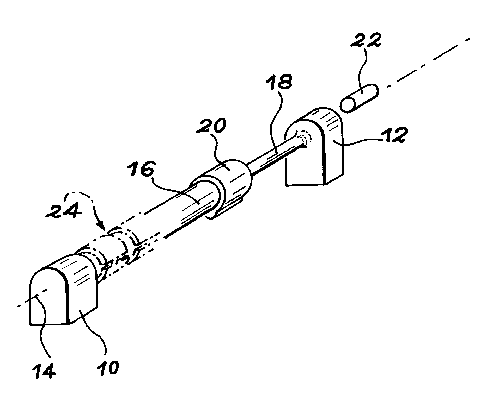
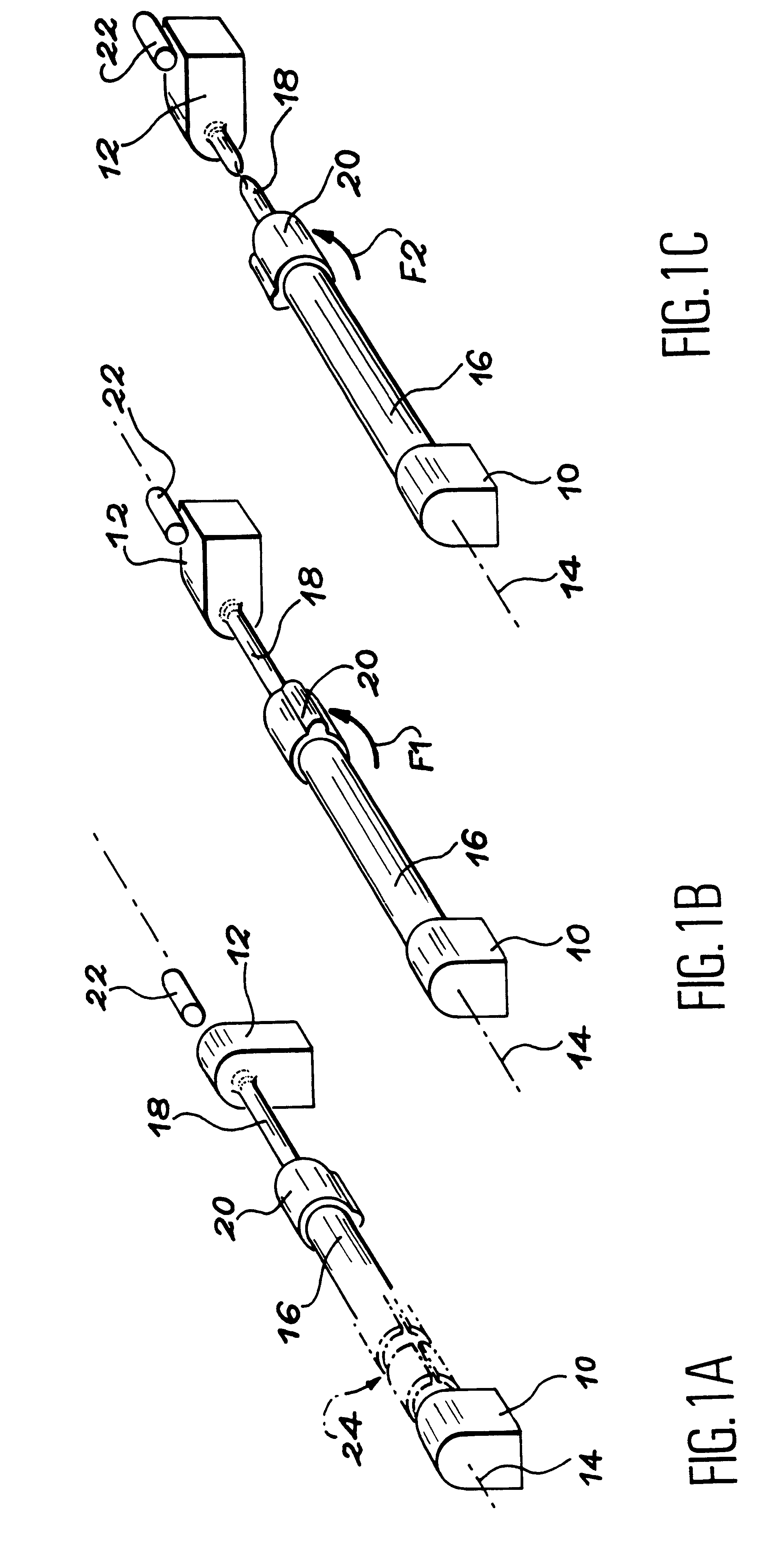
In FIGS. 1A to 1C, has been shown very diagrammatically a control device according to the invention, activating which induces a high torque allowing a high relative rotation angle to be generated between a first element 10, supposed fixed and a second element 12 to be engaged, around an axis 14.

The control device according to the invention mainly includes a torsion bar 16, of an extended cylindrical shape, made of a bistable shape memory alloy. The torsion bar 16 is centred on the axis 14 around which a pre-set relative rotation between the elements 10 and 12 is to be controlled.

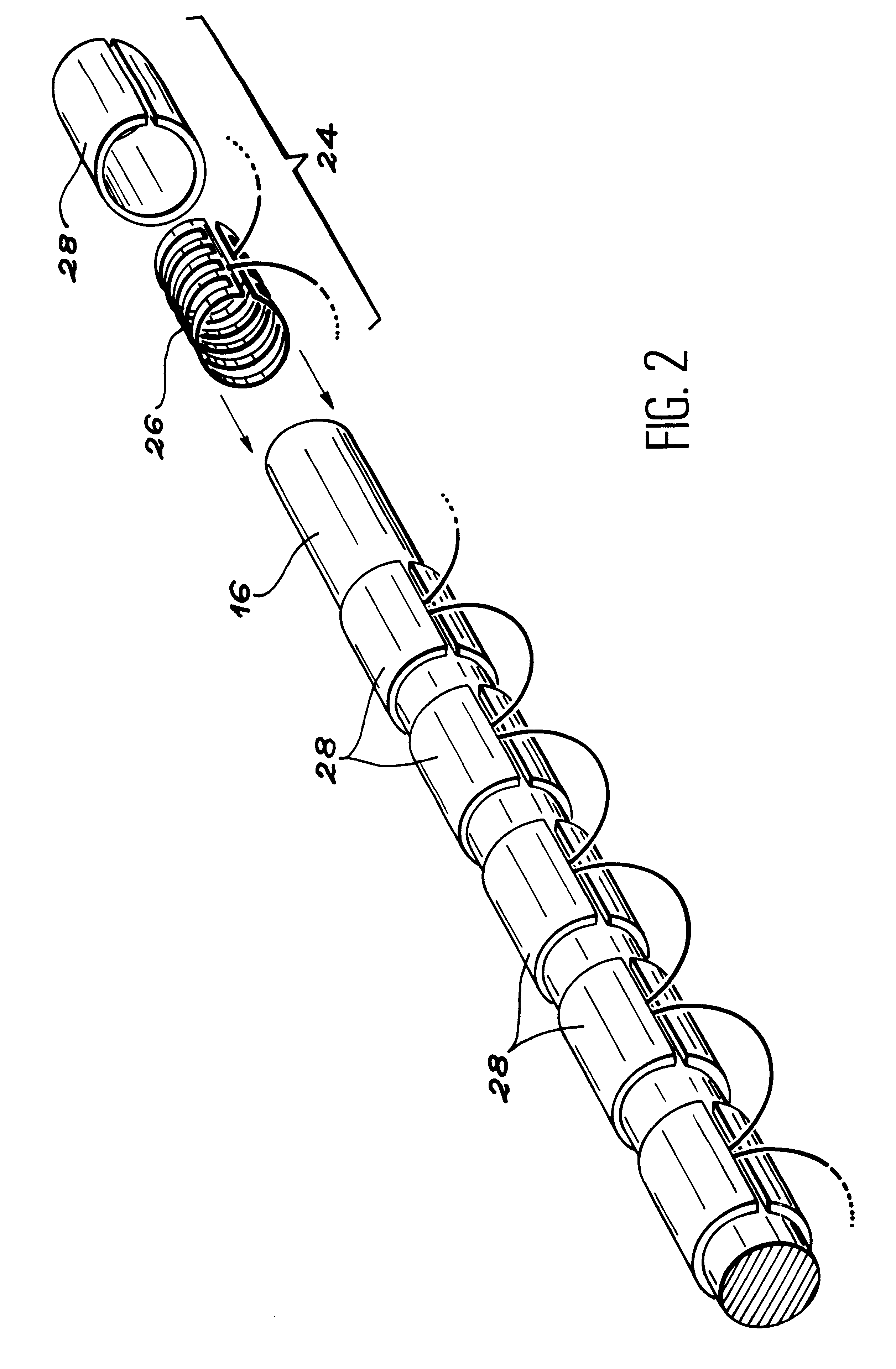
Heating means of the torsion bar 16 are provided, to control the activation of the device. These heating means are shown diagrammatically as 24 in FIG. 1A. They have not been shown in FIGS. 1B and 1C. These heating means 24 will be described subsequently by reference to FIG. 2.

A first end of the torsion bar 16 is connected directly in rotation to the fixed element 10. The second end of the bar 16 is connecte...


PUM


Abstract

To control a relative rotation between two elements (10, 12), such as flaps of a deployable mechanical structure, on a space vehicle, a torsion bar (16) is used made of a bistable shape memory alloy, heated over its whole length by heaters stuck on the bar and retained by hooping rings. A stop (22) restricts pivoting to the pre-set pivoting angle to be controlled. Excess pivoting of the torsion bar (16) is applied to a mechanical fuse (18), interposed between the bar and one (12) of the elements.

Description

The invention mainly concerns a device designed to control a relative rotation between two elements articulated relative to each other around a given axis.The invention also concerns a deployable mechanical structure, such as a solar array, a radiator or an antenna on a space vehicle, the deployment of which is controlled by means of one or more devices of this type.The invention finds a favoured application in the context of the folding mechanism of the different mechanical structures which are fitted to space vehicles (satellites, space probes, etc.). It can however also be used in other fields, since the deployment or folding up of a mechanical structure must be able to be controlled, with high torque and high. amplitude, by means of a compact device built into the structure.STATE OF THE ARTWhen a space vehicle is launched, it is necessary to keep a certain number of pieces of equipment such as solar arrays, radiators, antennae or the like, in the folded up position. Indeed, this...

Claims


Application Information

Patent Timeline
IPC IPC(8): B64G1/44B64G1/22B64G1/64B64G1/42E05F1/00E05F1/12F03G7/06
CPCB64G1/222B64G1/443B64G1/645E05Y2800/67E05F1/123E05Y2900/502E05Y2201/43E05F1/004
Inventor VEZAIN, GERARDKERHOUSSE, PATRICEVIALE, DANIELBAUDASSE, YANNICKREIMBOLD, FRAN.CEDILLA.OIS
Owner ALCATEL LUCENT SAS
Why Eureka
Try Eureka