Optical microswitch with rotary electrostatic microactuator

a microactuator and optical microswitch technology, applied in the field of optical microswitch, can solve the problems of relatively relatively slow bimetallic actuators, large number of output fibers, etc., and achieve the effect of low transmission loss

Inactive Publication Date: 2001-10-09
COHERENT INC
View PDF10 Cites 35 Cited by
  • Summary
  • Abstract
  • Description
  • Claims
  • Application Information

AI Technical Summary

Benefits of technology

Another object of the invention is to provide an optical microswitch of the above character which is capable of coupling visible or infrared light into an optical fiber with low transmission losses.
Another object of the invention is to provide an optical microswitch of the above character which has relatively fast switching times.

Problems solved by technology

All of switches are relatively large and expensive.
Such switch, however, is not easily extendable to a switch having a relatively large number of output fibers and bimetallic actuators are relatively slow.
Micromachined devices to tilt or rotate mirrors are known in the prior art, but suffer from various limitations.
All of such devices tend to have difficulty in maintaining flatness and smoothness in the mirror elements and may have difficulty in precise static positioning of the mirror due to hysteresis in the coupling between the electrostatic comb drive actuator in the plane of the substrate and the mirror element out of the substrate plane.

Method used


Image

  • Optical microswitch with rotary electrostatic microactuator
  • Optical microswitch with rotary electrostatic microactuator
  • Optical microswitch with rotary electrostatic microactuator

Examples


Embodiment Construction

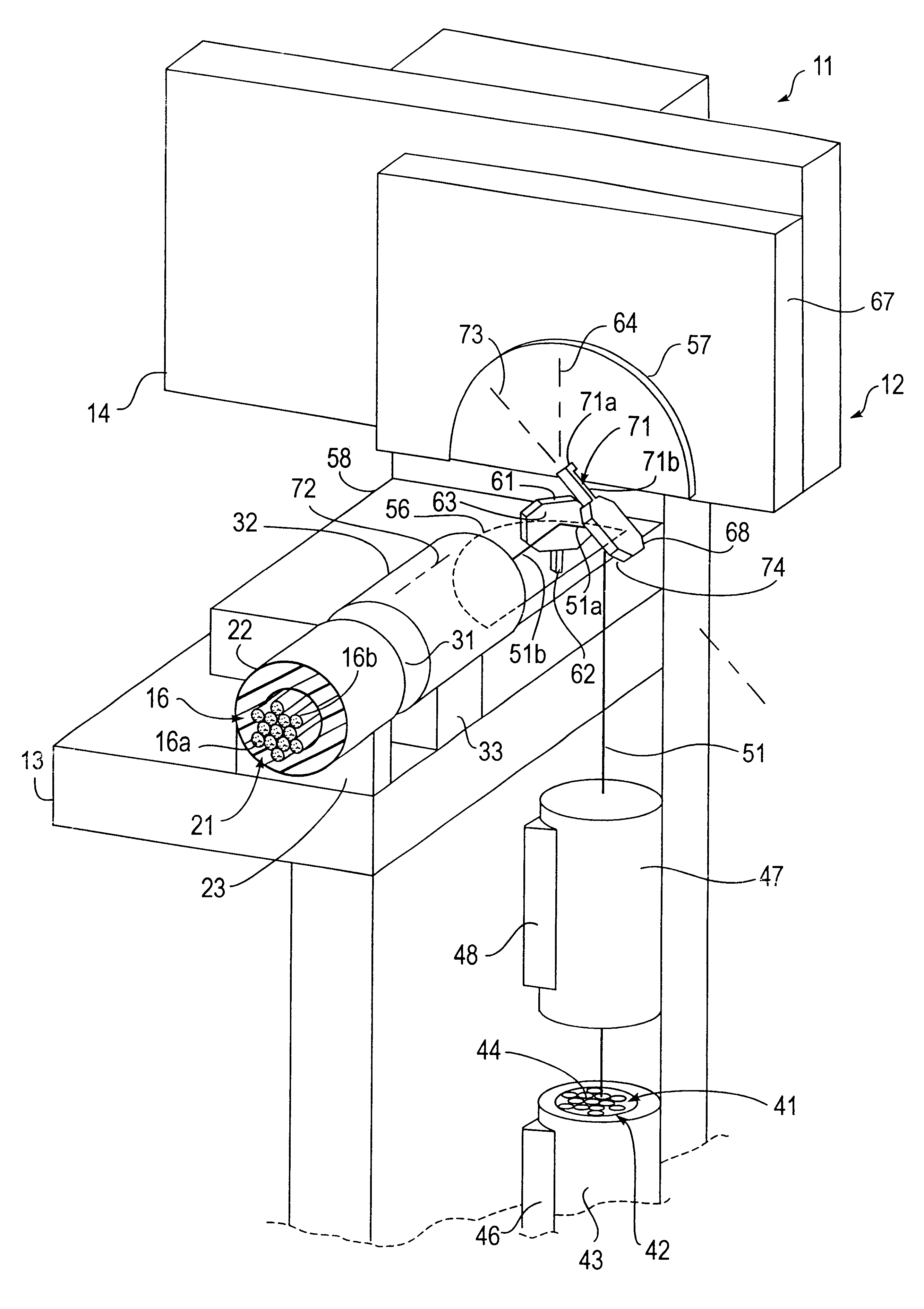
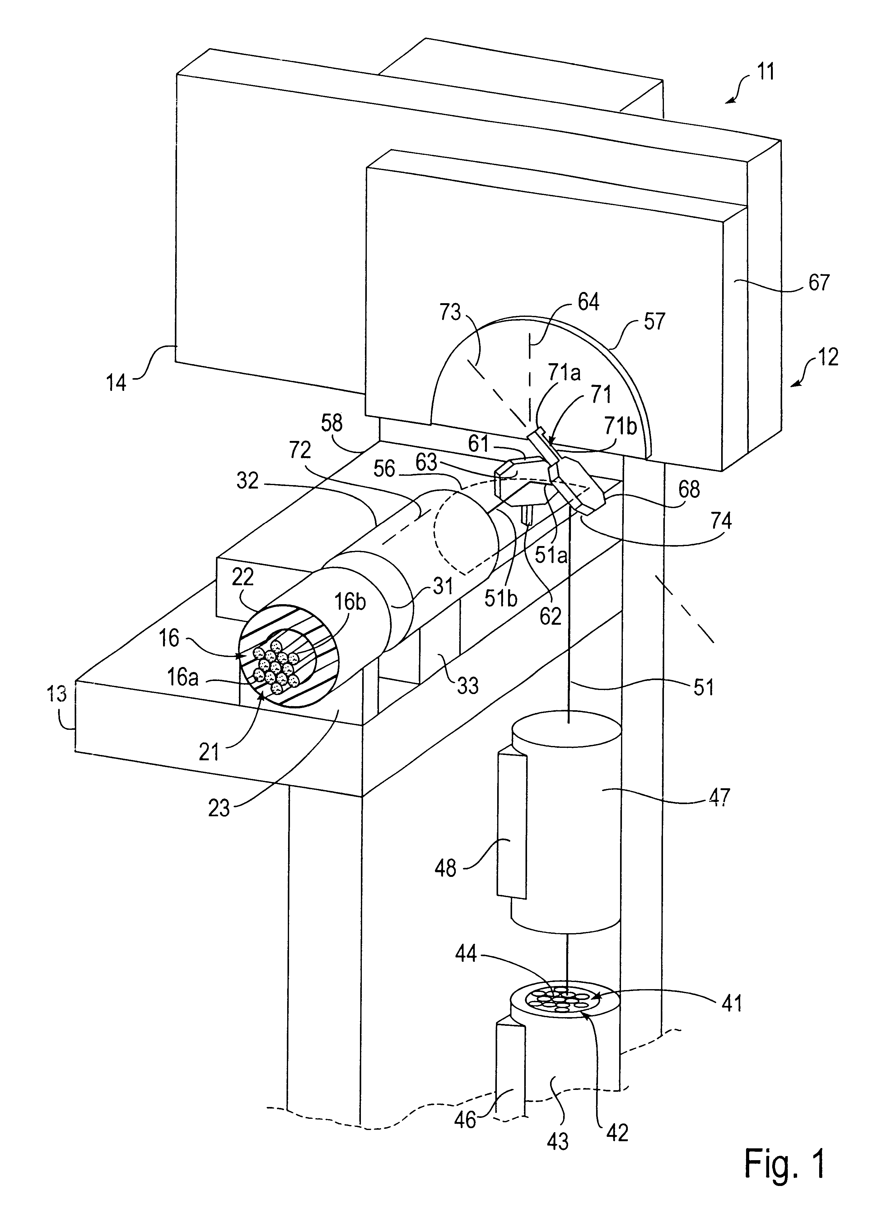
Optical microswitch 11, shown schematically in FIG. 1, is formed from a support body 12 of any suitable size and shape and made from any suitable material such as a ceramic material. Body 12 shown in FIG. 1 has a base 13 and a back 14 secured to the base and extending perpendicularly from the base. Support body 12 is optionally coupled to one and as shown a plurality of output optical fibers 16, which can be either single mode or multi-mode fibers. In this regard, a bundle 21 of such output fibers 16 is secured together by a tube 22 mounted on base 13 by any suitable means such as bracket 23. The plurality of optical fibers 16 includes first and second optical fibers 16a and 16b. Tube 22 and output bundle 21 terminate at an end 31. A conventional focusing lens such as a GRIN lens 32 is disposed adjacent the end 31 of the fiber optic output bundle 21 and is mounted to base 13 by any suitable means such as bracket 33. Lens 32 has a sufficient field of view to accommodate all of fibers...


PUM

PropertyMeasurementUnit
thicknessaaaaaaaaaa
thicknessaaaaaaaaaa
thicknessaaaaaaaaaa

Abstract

An optical microswitch comprising a support body and first and second output fibers carried by the body. A rotary electrostatic microactuator is carried by the body and extends in plane. A micromirror is disposed out of the plane. The microactuator has a mirror holder coupled to the micromirror and at least one comb drive assembly coupled to the mirror holder for driving the micromirror about an axis of rotation extending perpendicular to the plane between a first position for reflecting a laser beam to the first output fiber and a second position for reflecting the laser beam to the second output fiber.

Description

SCOPE OF THE INVENTIONThe present invention relates generally to optical microswitches and more particularly to optical microswitches utilizing electrostatic microactuators with comb drive assemblies.Optical switches have heretofore been provided. Many of such switches use macroscopic rotators. Switches utilizing electromagnetic motors have been disclosed to move either an input optical fiber or a refractive or reflective element interspersed between input and output optical fibers. Examples of such designs that use piezoelectric elements to move refractive or reflective elements are shown in U.S. Pat. Nos. 5,647,033 to Laughlin, U.S. Pat. No 5,748,813 to Buchin and U.S. Pat. No 5,742,712 to Pan et al. All of switches are relatively large and expensive.A micromachined optical switch is disclosed in U.S. Pat. No. 5,446,811 to Field et al. and uses a bimetallic element to displace an optical fiber into alignment with one or more optical fibers. Such switch, however, is not easily exte...

Claims


Application Information

Patent Timeline
Patent Type & Authority Patents(United States)
IPC IPC(8): G02B26/08G02B6/35G02B6/42G02B6/126G11B7/135G11B11/00G11B7/22G11B11/105G11B7/12G11B7/085G11B7/125H02N1/00H04B10/135G02B6/10G11B7/0037G11B7/00G11B7/09G11B7/14
CPCG02B6/126G02B6/3556G02B6/357G02B6/4246G02B26/0833G02B26/0841G02B26/085G02B26/0866G11B7/08564G11B7/1203G11B7/122G11B7/127G11B7/1362G11B7/1365G11B7/1372G11B7/1384G11B7/22G11B11/10532G11B11/10534G11B11/10541G11B11/10543G11B11/1058G11B11/10595H02N1/008G02B6/105G02B6/3512G02B6/3558G11B7/0037G11B7/08576G11B7/0901G11B7/14G11B11/10515G11B11/10554G11B11/10563G11B11/10569
Inventor HEANUE, JOHN F.JERMAN, JOHN H.
Owner COHERENT INC
Why Eureka
Try Eureka