Power regulator using active filter

a technology of power regulator and filter, applied in the direction of dc-ac conversion without reversal, process and machine control, instruments, etc., can solve the problems of low power factor and higher frequency noise, energy loss and harmonic noise, and the need to set the pulse period with a considerable margin

Inactive Publication Date: 2001-10-16
MITSUBISHI ELECTRIC SEMICON APPL ENG CORP +1
View PDF3 Cites 34 Cited by
  • Summary
  • Abstract
  • Description
  • Claims
  • Application Information

AI Technical Summary

Problems solved by technology

This will result in a lower power factor and higher frequency noise.
This presents a problem of requiring a high performance microcomputer 111 that can instantaneously calculate the consumed current and supply voltage to vary the pulse periods of the control pulses in accordance with the temperature change, circuit constant errors and the like.
Furthermore, because bringing the switching device 103 into conduction while the residual field of the coil 104 is not yet sufficiently reduced will cause a short circuit which will cause energy loss and harmonic noise, the pulse periods must be set with considerable margin.
This presents a problem of reducing the effect of the power factor improvement.

Method used


Image

  • Power regulator using active filter
  • Power regulator using active filter
  • Power regulator using active filter

Examples


embodiment 1

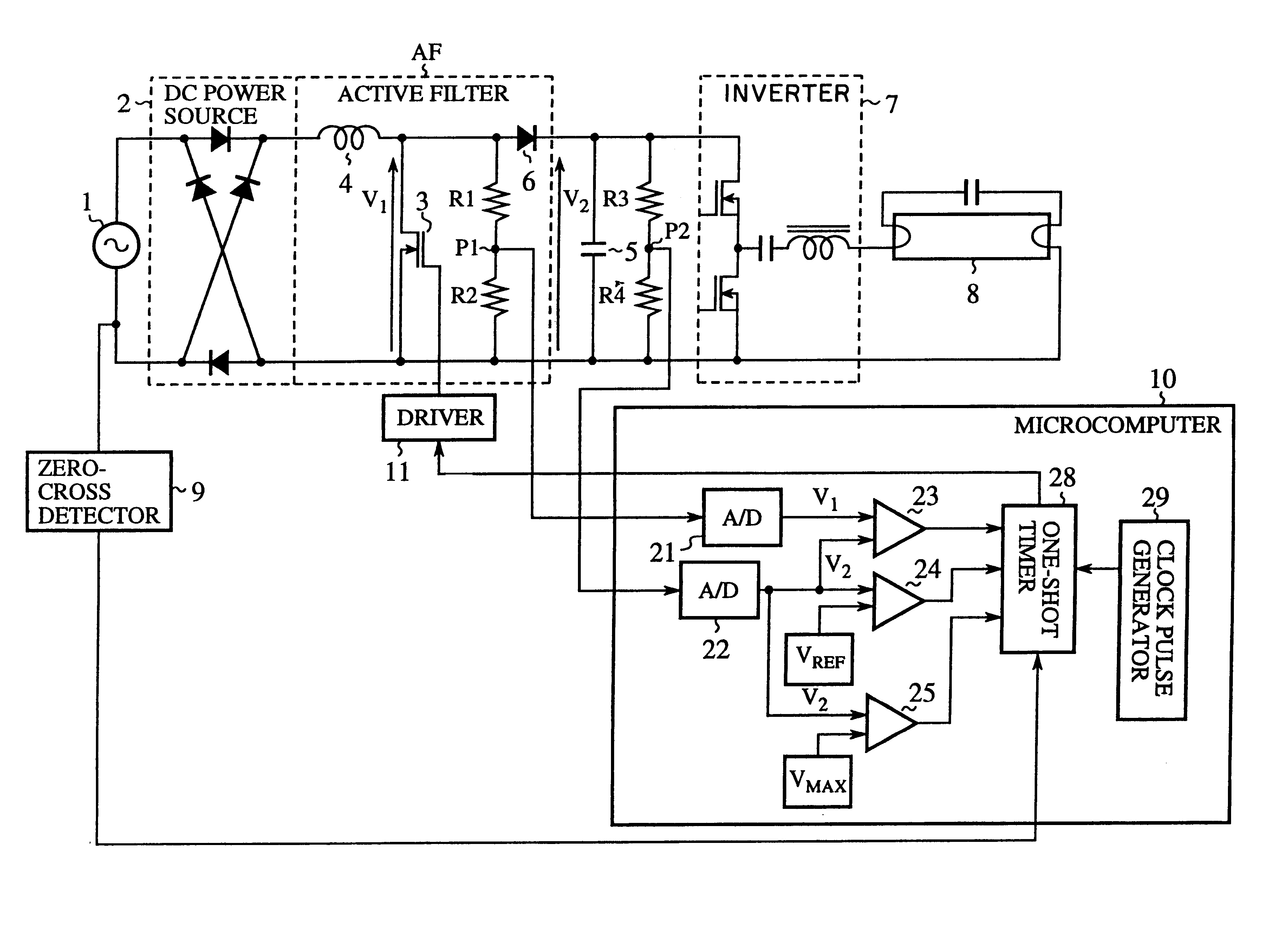
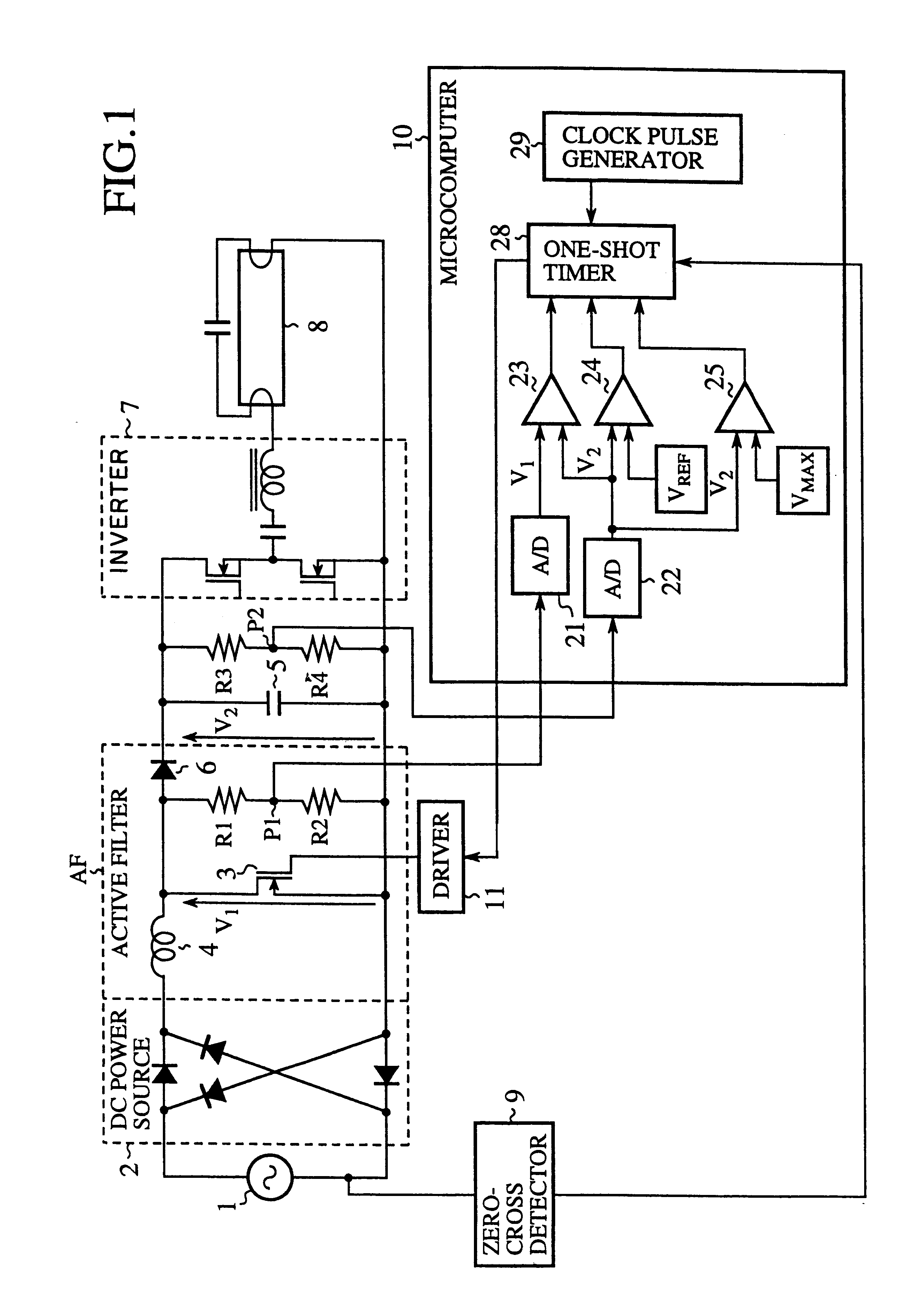
FIG. 1 is a circuit diagram showing an active filter control system by a microcomputer in accordance with the present invention. In FIG. 1, the reference numeral 1 designates an AC power supply; 2 designates a DC power source consisting of a full-wave rectifier; 3 designates a switching device connected in parallel with the DC power source 2 at its output side through a coil 4 of an active filter AF; 5 designates a charge-and-discharge capacitor connected in parallel with the switching device 3 through a backflow preventing diode 6; 7 designates an inverter functioning as a switching circuit for switching the charges of charge-and-discharge capacitor 5 and supplies its output to a fluorescent lamp 8; 9 designates a zero-cross detector for detecting zero-cross points of the AC current; 10 designates a microcomputer for receiving a detection signal fed from the zero-cross detector 9, 11 designates a driver for bringing the switching device 3 into conduction in response to a control si...

embodiment 2

FIG. 3 is a flowchart illustrating the operation of the present embodiment 2, in which the operation from step ST21 to step ST24 is the same as that from step ST1 to step ST4 of the foregoing embodiment 1, and hence the description thereof is omitted here. At step ST24, the comparator 23 decides whether the voltage V.sub.1 at the connecting point of the coil 4 and the backflow preventing diode 6 is lower than the voltage V.sub.2 charged in the charge-and-discharge capacitor 5, and subsequently the comparator 24 decides at step ST25 whether the voltage V.sub.2 is lower than the reference voltage V.sub.REF. If the charged voltage V.sub.2 is lower than V.sub.REF, the number of counting of the one-shot timer 28 is increased at step ST26 to broaden the pulse width.

On the other hand, if a decision is made at step ST25 that the voltage V.sub.2 is higher than V.sub.REF, the comparator 24 ensures this at step ST27, and if the result is positive (YES), the number of counting of the one-shot t...

embodiment 3

FIG. 4 is a flowchart illustrating the operation of the present embodiment 3, in which the operation from step ST31 to step ST37 is the same as that from step ST21 to step ST27 in the foregoing embodiment 2, and hence the description thereof is omitted here.

In the present embodiment 3, when a decision is made at step ST37 that the charged voltage V.sub.2 is higher than the reference voltage V.sub.REF, the comparator 25 makes a decision at step ST38 as to whether the voltage V.sub.2 exceeds the maximum reference voltage V.sub.MAX, and if the result is positive (YES), the one-shot timer 28 is controlled to stop generating the one-shot pulse at step ST40. In contrast, when the decision result is negative (NO), that is, when V.sub.2

According to the present embodiment 3, the charge-and-discharge capacitor 5, the voltage V.sub.2 of which can suddenly increase when the load consuming the power is r...


PUM


Abstract

A power regulator including a coil connected to an output of a DC power source for rectifying an AC voltage, a charge-and-discharge capacitor for charging a current supplied from the DC power source through the coil and a backflow preventing diode, a switching device connected to a connection point of the coil and backflow preventing diode in parallel with the DC power source, and a microcomputer for detecting a zero-cross point of the magnetic field energy generated in the coil or the current flowing through the coil, and for bringing the switching device into conduction in response to the detection of the zero-cross point. This makes it possible to solve a problem of a conventional device in that the switching period of the switching device cannot be changed in accordance with variables such as temperature change, errors in circuit constants and the like because switching periods of the switching device are predetermined values.

Description

1. Field of the InventionThe present invention relates to a power regulator for supplying power to a load efficiently, and more particularly to a power regulator that achieves this by using an active filter.2. Description of Related ArtAs shown in FIG. 6, a power supply for various electrical appliances acquires a DC voltage from a commercial AC line using a rectifier circuit 91 and a large capacity smoothing capacitor 92. The rectifier circuit 91 instantaneously grabs power from the AC line when the AC voltage exceeds a capacitor charged voltage. An inverter 93 operating as a switching circuit converts the DC voltage charged by the capacitor to an AC voltage, and supplies it to a load 94. As clearly seen from FIG. 7, the power is captured only around the peaks of the AC line voltage as illustrated by a solid waveform. Therefore, the effective power is considerably lower than the apparent power of the AC power supply, resulting in a rather low power factor of the electrical applianc...

Claims


Application Information

Patent Timeline
Patent Type & Authority Patents(United States)
IPC IPC(8): H02M1/00H05B41/28H02J1/00H02M7/12H02M7/48
CPCH02M1/4225H05B41/28H02M2001/007Y02B70/126Y02B70/10H02M1/007
Inventor TAKITA, HIROKI
Owner MITSUBISHI ELECTRIC SEMICON APPL ENG CORP
Why Eureka
Try Eureka