Stent crimper apparatus with radiation shied

a crimper and stent technology, applied in the field of stent crimper apparatus with radiation shied, can solve the problems of balloon and/or stent damage, balloon and/or stent loss, and may not perform the other way as desired,

Inactive Publication Date: 2001-10-30
ISOSTENT
View PDF4 Cites 107 Cited by
  • Summary
  • Abstract
  • Description
  • Claims
  • Application Information

AI Technical Summary

Benefits of technology

Accordingly, a shielded stent crimping apparatus is provided for crimping a deformable radioactive stent onto a deployment device which includes a first jaw member defining a shielded first compression surface, and an opposed, second jaw member defining a shielded second compression surface oriented opposite the first compression surface. The first and second compression surfaces being adapted to collectively form an elongated guide bore formed for axial receipt of the deformable stent and the deployment device therein. A shield assembly defines an opening into the bore, and cooperates with the first and second jaw members to substantially prevent radioactive particles emitted by the radioactive stent from passing out of the crimping apparatus. An operating mechanism is provided operatively coupled to the first and second jaw members for selective movement between a loading condition and a crimping condition. In the loading condition, the uncrimped stent and the deployment device may be inserted through the opening and into the bore. In the crimping condition, the deformable stent is radially compressed onto the deployment device between the first and second compression surfaces.

Problems solved by technology

Problems occur, however, when the dilatation of the occlusion forms fissures, flaps and / or dissections which may ultimately cause reclosure or restenosis of the vessel.
The proper crimping of a stent about a balloon catheter, however, is a technique acquired only through practice and can be affected by a variety of subjective conditions.
Too much or too little pressure may be applied and the balloon and / or stent may be damaged, lost, or may not otherwise perform as desired during the procedure.
In contrast, the physician may not apply sufficient crimping pressure to the stent to load it onto the balloon.
During advancement through the vessel or upon deployment, an insufficiently crimped stent may slip or rotate on the catheter during, or in the worst case scenario, come off the balloon catheter entirely; the result of which is not desirable.
Thus, maintaining such an inventory is not only difficult to store, but can be very expensive as well.
The performance of these tools, however, is not completely satisfactory since there is still a wide divergence between application force, profile and stent diameter.
Problems arise when excessive crimping forces are applied to the crimp pliers which can damage the stent and / or balloon catheter.
This is especially problemsome given the minute size of the stents which are typically on the order of about one (1) mm to four (4) mm in diameter before crimping.
Non-uniformity of the crimping may also be experienced as well as the inability to determine when a reliable and uniform crimp has been achieved.
Moreover, these designs are inadequate to handle radioactive or radioisotope embedded stents since they typically cause the physicians and / or laboratory technicians to be subjected to excessive radiation exposure.

Method used


Image

  • Stent crimper apparatus with radiation shied
  • Stent crimper apparatus with radiation shied
  • Stent crimper apparatus with radiation shied

Examples


Embodiment Construction

While the present invention will be described with reference to a few specific embodiments, the description is illustrative of the invention and is not to be construed as limiting the invention. Various modifications to the present invention can be made to the preferred embodiments by those skilled in the art without departing from the true spirit and scope of the invention as defined by the appended claims. It will be noted here that for a better understanding, like components are designated by like reference numerals throughout the various figures.

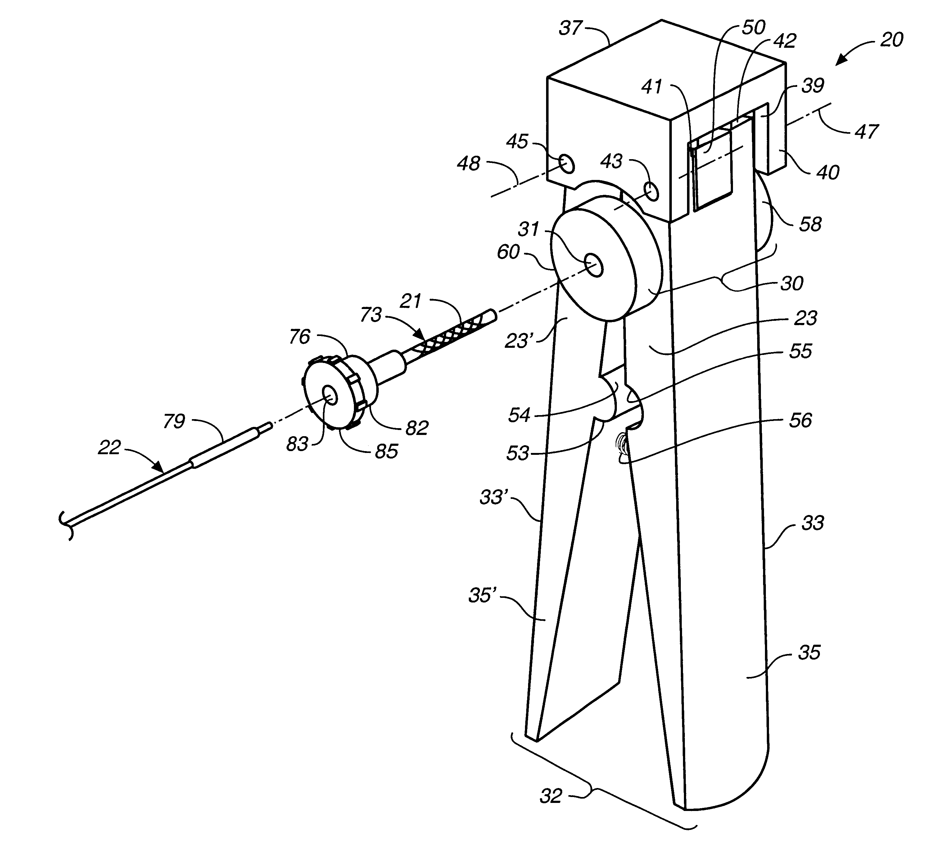
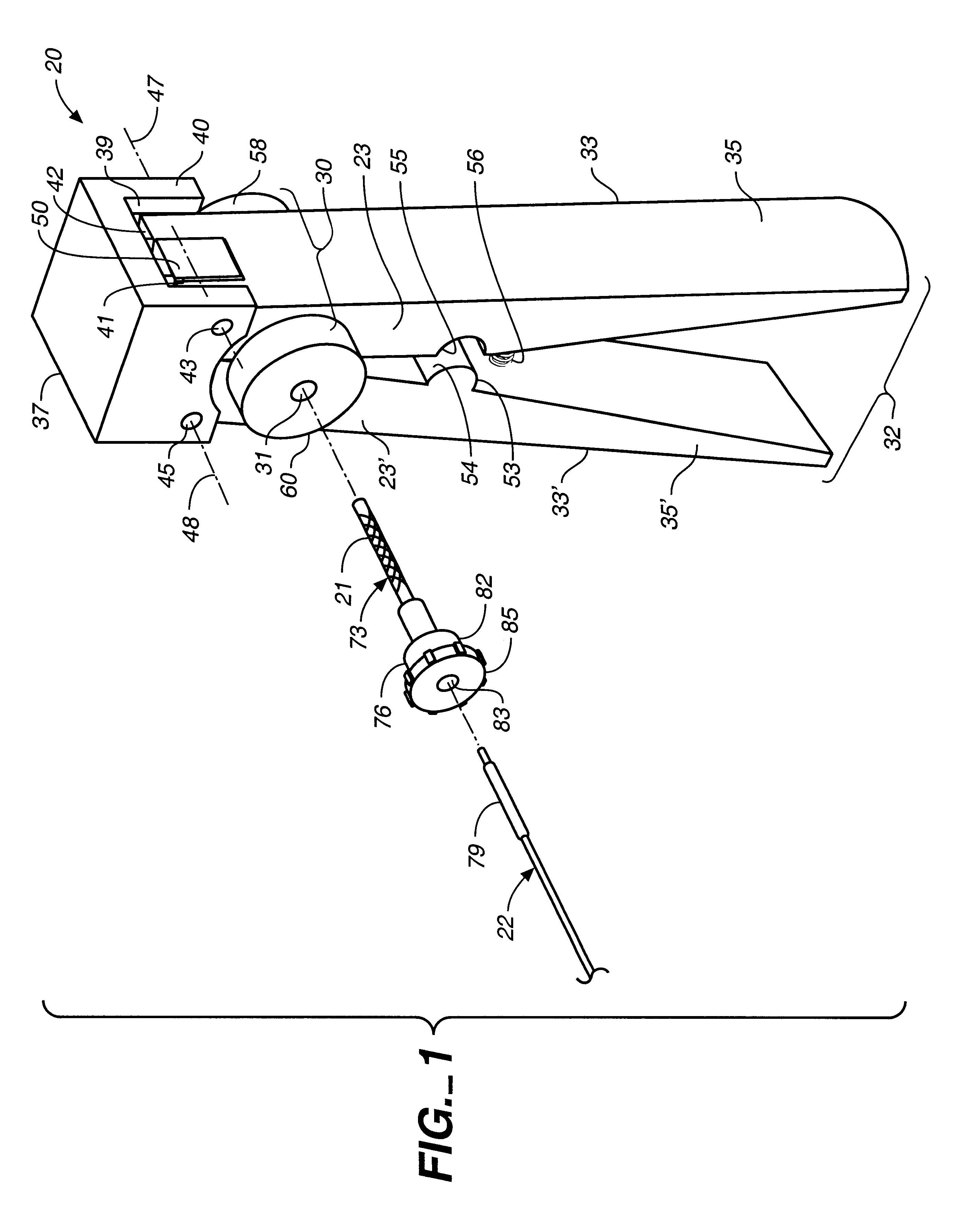
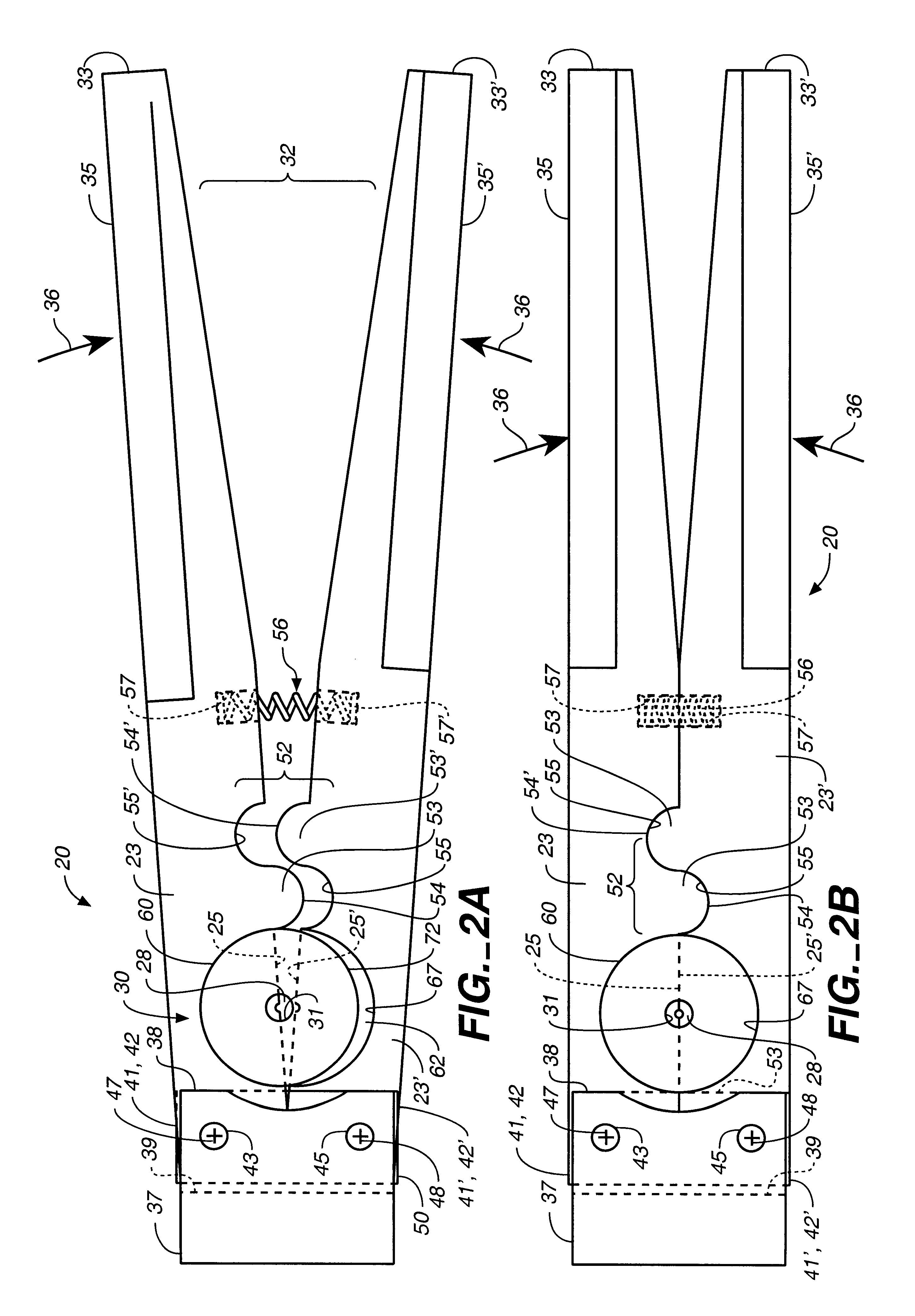
Attention is now directed to FIGS. 1, 2 and 5, where a stent crimping apparatus, generally designated 20, is provided for crimping a deformable radioactive stent 21 onto a deployment device 22. The crimping apparatus 20 includes a first jaw member 23 defining a shielded first compression surface 25, and an opposed, second jaw member 23' defining a shielded second compression surface 25' oriented opposite the first compression surface 25....


PUM


Abstract

A stent crimping apparatus for crimping a deformable radioactive stent onto a deployment device which includes a first jaw member defining a shielded first compression surface, and an opposed, second jaw member defining a shielded second compression surface oriented opposite the first compression surface. The first and second compression surfaces are adapted to collectively form an elongated guide bore formed for axial receipt of the deformable stent and the deployment device therein. To protect against exposure to the radioactive stent, a shield assembly is provided defining an opening into a bore therein which is formed and dimensioned for longitudinal receipt of the deformable stent in an uncrimped condition. A shield assembly defines an opening into the bore, and cooperates with the first and second jaw members to substantially prevent radioactive particles emitted by the radioactive stent from passing out of the crimping apparatus. An operating mechanism is operatively coupled to the first and second jaw members for selective movement between a loading condition and a crimping condition. In the loading condition, the uncrimped stent and the deployment device may be inserted through the opening and into the bore. In the crimping condition, the deformable stent is radially compressed onto the deployment device between the first and second compression surfaces.

Description

The present invention relates, generally, to intravascular stents and, more particularly, to stent crimping apparatus with radiation shields for radioactive stents.Percutaneous Transluminal Angioplasty (PTA) is a medical procedure for widening a stenosis or constriction of a bodily passage. The most common application is to widen the passage of a blood vessel, such as an artery, which has been constricted by the build-up of cholesterol fats or atherosclerotic plaque. When this medical procedure is applied to a coronary artery, it is referred to as Percutaneous Transluminal Coronary Angioplasty (PTCA).Typically, a tip mounted balloon of a balloon catheter is advanced over a guidewire to the stenosis. Once the balloon catheter is properly positioned, the balloon is inflated to compress the plaque against the vessel walls and widen the stenosis. Problems occur, however, when the dilatation of the occlusion forms fissures, flaps and / or dissections which may ultimately cause reclosure or...

Claims


Application Information

Patent Timeline
Patent Type & Authority Patents(United States)
IPC IPC(8): A61F2/06B25B7/00B25B27/14A61F2/00A61F2/84
CPCA61F2/958B25B7/00B25B27/146A61F2002/9522A61F2210/0095A61F2/9522
Inventor CAMPBELL, THOMAS H.TURNLUND, TODD H.CHANG, ROBERT T.
Owner ISOSTENT
Why Eureka
Try Eureka