
Pointer instrument

a pointer instrument and carrier technology, applied in the direction of instruments, measurement device, measurement apparatus components, etc., can solve the problems of complicated production and assembly, affecting the functional reliability of the pointer instrument, and the sleeve and the carrier are connected

Inactive Publication Date: 2001-11-13
MANNSMANN VDO
View PDF16 Cites 23 Cited by
  • Summary
  • Abstract
  • Description
  • Claims
  • Application Information

AI Technical Summary

Benefits of technology

According to the invention the novel pointer instrument is particularly simply constructed. Power supply to the illuminating means is thus no longer carried out, as in the case of the known pointer instrument, via the pointer shaft, which is generally produced from metal, or via the compression spring, but rather via the conductors which run continuously from the connecting contacts to the contact surfaces. In this manner, the number of contact points is kept as small as possible, which increases the functional reliability of the novel pointer instrument. The use of electrically conductive plastic contributes to the functional reliability of the pointer instrument, since electrically conductive plastic is not permanently covered by an electrically insulating oxide layer, as is the case with metal, for example. A further advantage of the connecting sleeve is that it has a particularly low weight, so that it does not hamper the movement of the pointer as a result of its mass moment of inertia. The connecting sleeve can be produced, for example, completely by plastic injection molding, so that subsequent assembly is dispensed with. As a result, the connecting sleeve is configured particularly cost-effectively.
The illuminating means could be, for example, an incandescent filament. However, the illuminating means has a particularly low energy consumption and is able to illuminate the pointer well if it is an LED chip. Furthermore, such an LED chip has a particularly long service life, as compared with other illuminating means, so that exchange of the illuminating means during the service life of the pointer instrument only has to be carried out infrequently, if at all.
The illuminating means can be exchanged easily if, according to another advantageous feature of the invention, the connecting sleeve has, at its end facing the pointer, a mount which is upright, of C-shaped cross section, open at the top and in the direction of the pointer flag and has contact surfaces arranged in it, and if the illuminating means is arranged on a circuit board which is designed to be pushed into the mount. In this manner, the connecting sleeve may be produced as a standard component for different pointer instruments which are intended to have pointers that have different brightnesses or various colors.
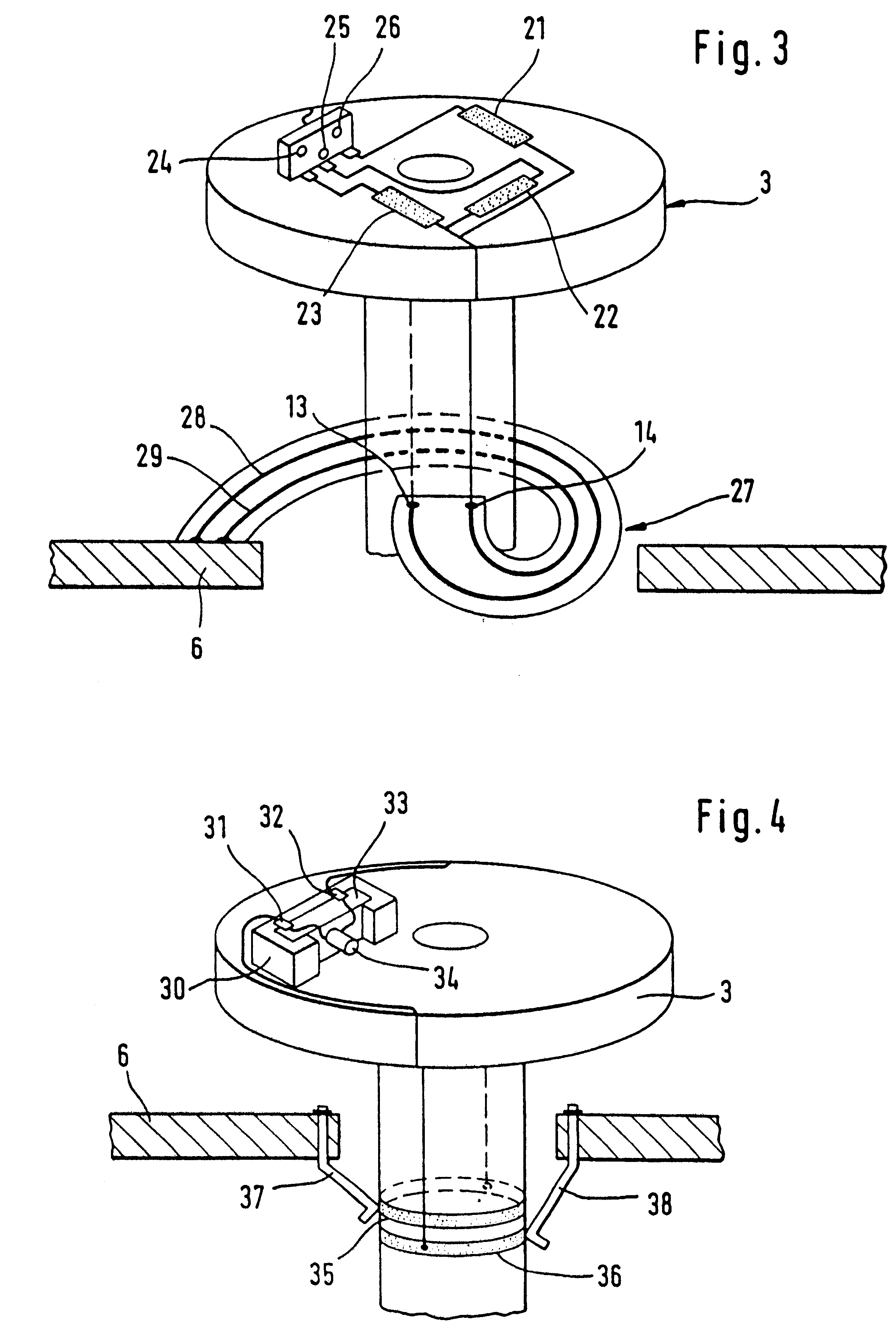
Typically the pointer of the novel pointer instrument pivots only over a range of 120.degree. to 270.degree.. In this case, the electrical connection between the connecting sleeve and the power supply is particularly simply configured, according to another advantageous feature of the invention, if the connecting sleeve has sinuous wires of conductive plastic that are injection molded on. By virtue of the sinuous shape, the wires can be bent and stretched easily, whereby the movement of the pointer shaft is not impeded.
In the case of pointers that pivot over a particularly large range, contact may be made with the connecting sleeve, as in the known pointer instrument, using spiral springs, which would then have to be soldered or plugged onto the connecting sleeve. These spiral springs either could have a particularly low spring force or could be arranged in pairs and in opposite directions. However, contact is made between the connecting sleeve and the power supply very simply if the pointer instrument has a flexible, spiral sheet with conductor tracks printed on it, and the conductor tracks are soldered or clamped to the power supply and to the connecting contacts of the connecting sleeve. Such a sheet can be produced particularly cost-effectively, and has a barely perceptible spring force.
According to another advantageous feature of the invention, the connecting sleeve is quick to assemble and disassemble if the connecting sleeve has slip rings extending around its circumference at different heights, against which prestressed contact springs rest, these springs being connected to the lower supply of the pointer instrument. Since in this case the number of slip rings is limited only by the dimensions of the connecting sleeve, it is possible here to insert a plurality of illuminating means very easily and to activate them differently. For example, a plurality of illuminating means of different colors can be inserted, and the pointer can, in different states, be illuminated in different colors.

Problems solved by technology

The disadvantage with such a pointer instrument is that the connecting sleeve and the carrier consist of very many components, which are complicated to produce and to assemble.
Furthermore, there is an unnecessarily large number of contact points between the power supply and the illuminating means, and these impair the functional reliability of the pointer instrument.
As a result, the connecting sleeve is configured particularly cost-effectively.
However, the illuminating means has a particularly low energy consumption and is able to illuminate the pointer well if it is an LED chip.
Furthermore, such an LED chip has a particularly long service life, as compared with other illuminating means, so that exchange of the illuminating means during the service life of the pointer instrument only has to be carried out infrequently, if at all.
Furthermore, in this case the risk of contamination of slip rings or of breakage of springs and sheets is ruled out.

Method used


Image

  • Pointer instrument
  • Pointer instrument
  • Pointer instrument

Examples


Embodiment Construction

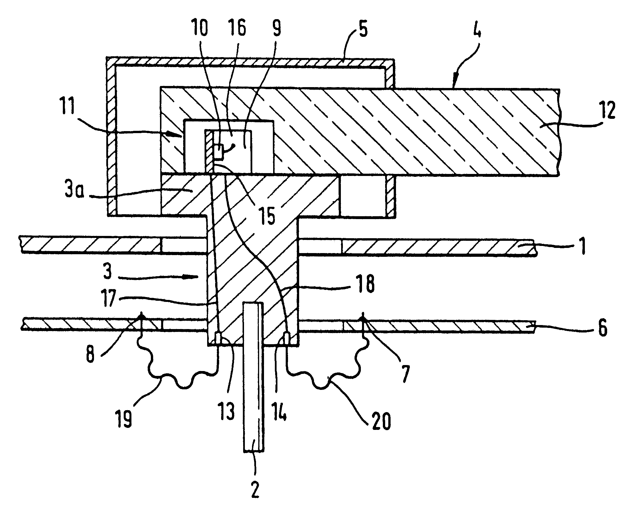
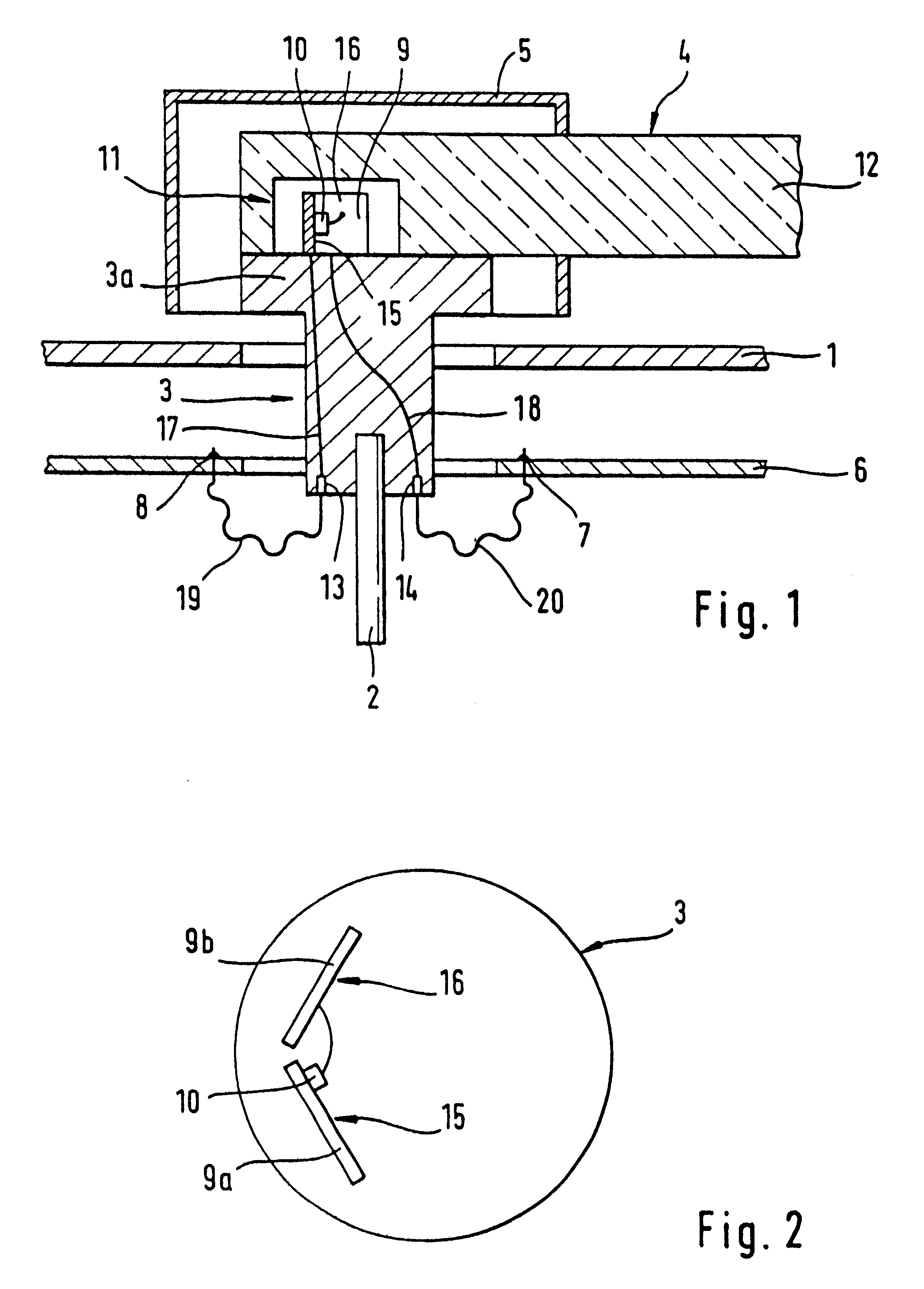
FIG. 1 shows a detail from a pointer instrument having a dial face 1, which is penetrated by a connecting sleeve 3 that is plugged onto a pointer shaft 2. Fastened to the connecting sleeve 3 is a pointer 4. The connecting sleeve 3 forms a carrier 3a at an end of the sleeve 3 facing the pointer 4. In the region of the connecting sleeve 3, the pointer 4 has a cap 5 made of an opaque material. Arranged underneath the dial face 1 is a circuit board 6 having contacts 7, 8 for a power supply. Located on the upper side of the connecting sleeve 3 is an upright reflector 9 having an illuminating means 10, these projecting into a recess 11 in the pointer 4. The reflector 9 and the illuminating means 10 are aligned such, that light radiated by them is radiated directly into a flag 12 of the pointer 4.

The connecting sleeve 3 is produced from nonconductive plastic and has conductors 17, 18 of conductive plastic which run continuously from connecting contacts 13, 14 on its underside to contact su...


PUM


Abstract

A pointer instrument having a connecting sleeve (3) which holds an essentially transparent pointer (4), and an illuminating means (10) that radiates directly into a flag (12) of the pointer (4), the connecting sleeve (3) having conductors (17), 18) and contact surfaces (15, 16) of conductive plastic. At its end facing away from the pointer (4), the connecting sleeve (3) has connecting contacts (13, 14) for making contact with a power supply of a circuit board (6).

Description

FIELD AND BACKGROUND OF THE INVENTIONThe invention relates to a pointer instrument having a pointer shaft that deflects an essentially transparent pointer, having an illuminating means that radiates directly into a flag of the pointer and, having a carrier which is fastened to the pointer shaft. The carrier holds the pointer and has contact surfaces for making contact with the illuminating means, having a connecting sleeve that has connecting contacts for a connection to a power supply, and having conductors to connect the connecting contacts and the contact surfaces.Such a pointer instrument, in which the illuminating means, together with the pointer, is fastened to the carrier and radiates directly into the pointer flag, is known. In the case of the known pointer instruments, the carrier has an electrically conductive inner body that is connected to one pole of the illuminating means, and an electrically conductive outer body that is connected to the other pole of the illuminating...

Claims


Application Information

Patent Timeline
Patent Type & Authority Patents(United States)
IPC IPC(8): G01D11/28G01D13/22G01D13/28
CPCG01D11/28B60K37/02Y10S116/36B60K35/60B60K2360/336
Inventor OLBRICH, HELMUTKOLIBIUS, HANSNOLL, HEINRICHZECH, STEPHAN
Owner MANNSMANN VDO
Learn More