
Apparatus and method for generating skeleton-based dynamic picture images as well as medium storing therein program for generation of such picture images

a dynamic picture and image technology, applied in the field of apparatus and method for generating skeleton-based dynamic picture images, and the medium storing therein program for generating such picture images, can solve the problems of inability to adapt the prior known approach to use with tv games, the work load of an associative central processing unit (cpu), and the difficulty of moving a model(s) on a real time basis

Inactive Publication Date: 2001-11-13
KONAMI DIGITAL ENTERTAINMENT CO LTD
View PDF5 Cites 71 Cited by
  • Summary
  • Abstract
  • Description
  • Claims
  • Application Information

AI Technical Summary

Benefits of technology

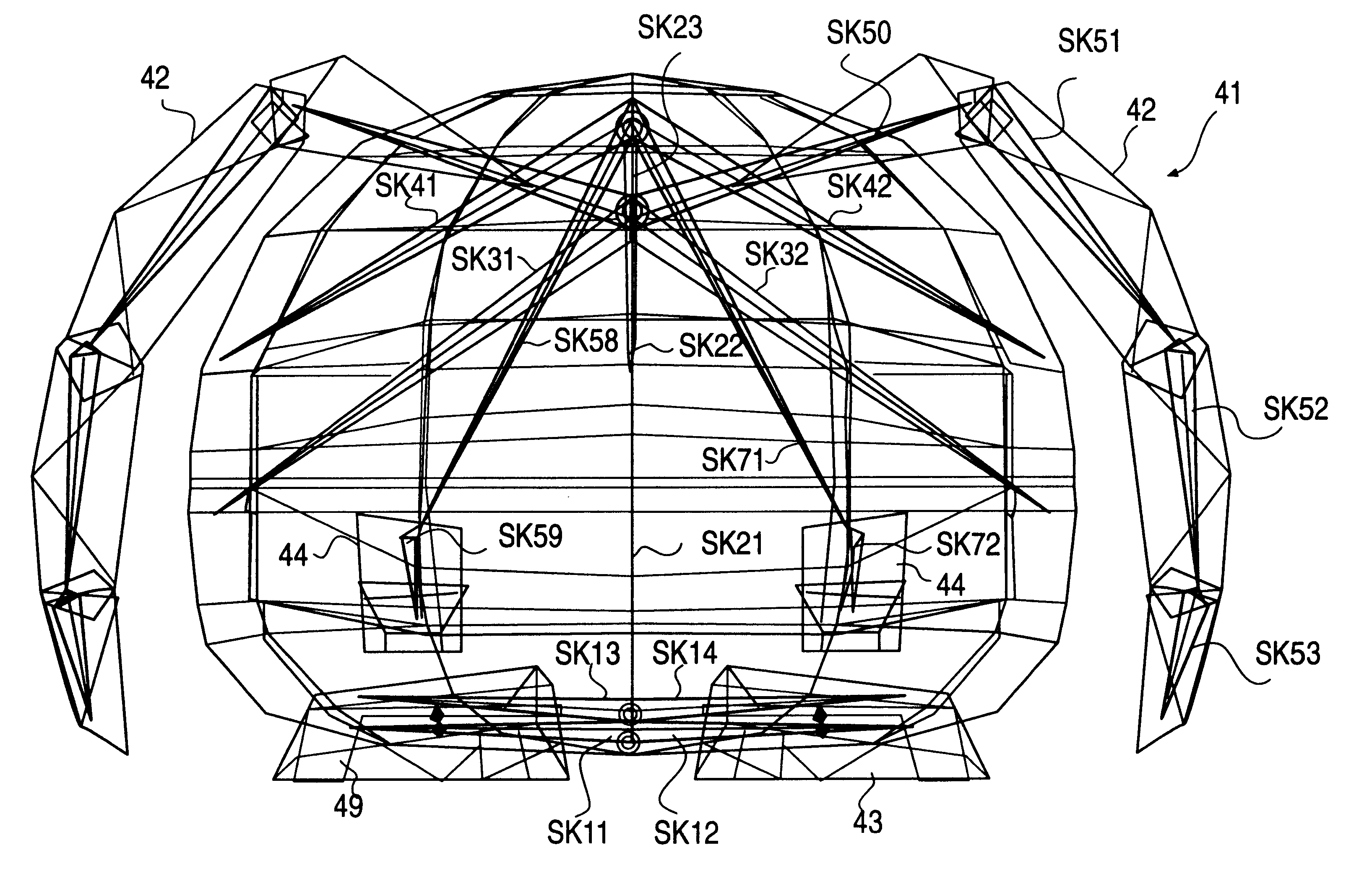
It is another object of the invention to provide improved apparatus and method for generating skeleton-based 3D dynamic picture images of animation characters as modelled or deformed to represent natural creatures including human and animals, capable of permitting more natural and precise actions by supplying joints and skeletons to those constituent portions without inherent joints and bones thus enabling development of more interesting idea-rich TV games.
In accordance with a yet further aspect of the present invention, a record carrier medium is provided which stores therein a program for generation of a skeleton-based dynamic picture image by providing skeletons for use in defining the relative positional attitude of one or several polygons which are display elements of a character object, causing each skeleton to be associated with a model that essentially consists of an ensemble of predefined number of polygons, and calculating based on rotational mount data given in response to key operations as one of elements defining the skeletons a display position of a model associated with each skeleton on a 2D display screen, the program further comprising defining as part of the character object a deformable constituent portion structured from one or a plurality of models, adding timebase rotational amount data to each of those skeletons corresponding to the constituent portion, and allowing corresponding models to be given with mutually related movement or motions.

Problems solved by technology

Where an attempt is made to precisely represent movement or motions of a three-dimensional (3D) model structured from polygons, the resulting polygons increase in number causing workload of an associative central processing unit (CPU) to likewise increase when the CPU is designed to calculate endpoint coordinates on a mere step-by-step bases (vertex difference animation scheme), which in turn makes it difficult to move a model(s) on a real time basis.
Especially, such prior known approach is not adaptable for use with TV games which are designed to allow more than one model to exhibit various kinds of motions or "actions" in rapid response to game player's operations of several types of key buttons of his or her game machine.
The prior art multijoint structure based motion creation scheme with graphical joints being given to those joint locations of a real body offers capability of merely relatively simple actions of an animation character being displayed in operative corporation with angle data preset to skeletons, such as tilting and expansion / shrinking motions of its back, arms and legs--namely, partial bending and stretching actions--and also remains ineffective for providing more complicated actions to such character as presently displayed.
Accordingly, applying to TV games such animation character with mere partial bending / stretching motion capabilities makes it impossible to accomplish a wide variety of character's complicated motions or actions as demanded by operators or "game players," which might disadvantageously serve as a serious bar to creation of idea-rich and enjoyable TV game software.

Method used


Image

  • Apparatus and method for generating skeleton-based dynamic picture images as well as medium storing therein program for generation of such picture images
  • Apparatus and method for generating skeleton-based dynamic picture images as well as medium storing therein program for generation of such picture images
  • Apparatus and method for generating skeleton-based dynamic picture images as well as medium storing therein program for generation of such picture images

Examples


Embodiment Construction

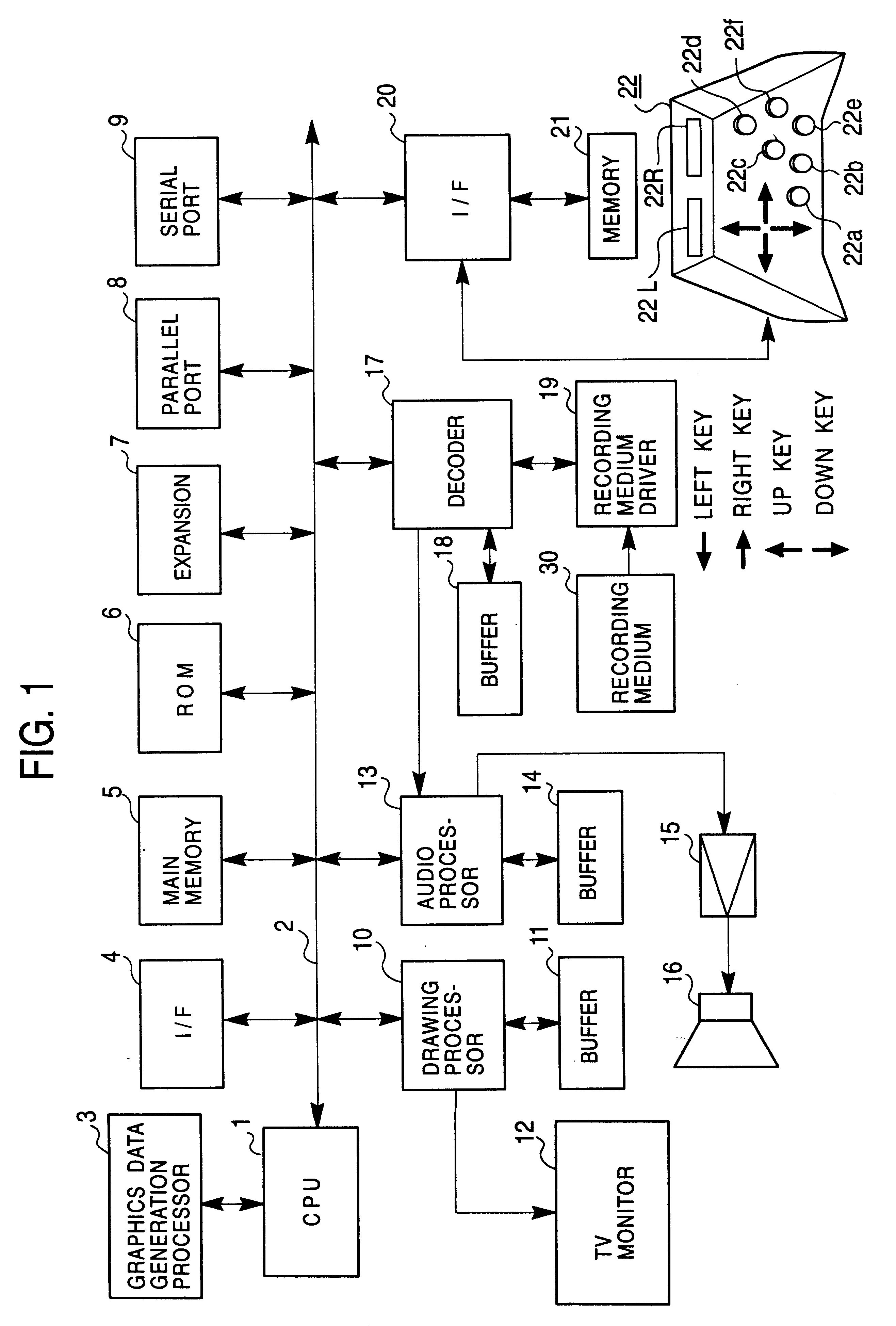
FIG. 1 is a diagram showing a configuration of one typical television (TV) game system in accordance with one preferred embodiment of the instant invention.

The game system shown in FIG. 1 includes a game machine main body and an associative recording or storage medium 30 prestoring therein software programs and data. The game machine main body includes a CPU 1, and a bus 2 connected to the CPU 2 which bus has address, data and control bus lines. The game machine also includes a graphics data generation processor 3, interface circuit 4, main memory 5, read-only memory (ROM) 6, expansion processing circuit 7, parallel port 8, serial port 9, graphics drawing processor 10 with buffer 11, audio processor 13 with buffer 14, decoder 17 with buffer 18, interface circuit 20 and memory 21, these components being interconnected with the bus 2 as shown in FIG. 1. Further, a TV monitor unit 12 is connected to drawing processor 10; a loudspeaker 16 is connected to audio processor 13 via an amplif...


PUM


Abstract

Enabling an animation character object, which is pictorially deformed by computer graphics techniques to visually represent human body or animal or the like in the form of a caricature or model, to offer precise and more natural motions at its selected constituent portions that have inherently no joints and no bones by giving thereto joints and skeletons. To this end, apparatus and method for generating skeleton-based animation images in accordance with the principles of the invention include solving means as follows. A face section of a cubic character object is provided with auxiliary skeletons as vertically coupled together. Skeletons are provided which extend from respective endpoints of such auxiliary skeletons and are coupled defining an umbrella shape as a whole. These skeletons are associated with models each consisting of an ensemble of polygons for rendering the character deformable by changing rotation amount of each skeleton.

Description

1. Field of the InventionThe present invention relates to an apparatus and method for generating dynamic picture images by effectuating polygon mapping using skeletons which are adaptable for use in advanced computer graphics architecture including but not limited to home-use television (TV) game machines. The invention also relates to storage or record media storing therein a software program for creation of such movable picture images for visual presentation on the screen of an associated display unit.2. Description of the Related ArtWhere an attempt is made to precisely represent movement or motions of a three-dimensional (3D) model structured from polygons, the resulting polygons increase in number causing workload of an associative central processing unit (CPU) to likewise increase when the CPU is designed to calculate endpoint coordinates on a mere step-by-step bases (vertex difference animation scheme), which in turn makes it difficult to move a model(s) on a real time basis....

Claims


Application Information

Patent Timeline
Patent Type & Authority Patents(United States)
IPC IPC(8): G06T15/70A63F13/52G06T13/40A63F13/55
CPCG06T13/40A63F2300/6607
Inventor ISHIKAWA, HIROTAKAHARUYAMA, KAZUNORINAKAZAWA, KAZUHIDE
Owner KONAMI DIGITAL ENTERTAINMENT CO LTD
Learn More