
Residue division multiplexing system and apparatus for discrete-time signals

a discrete-time signal and multiplexing technology, applied in the field of multiplexing system and multiplexing and demultiplexing apparatuses for telecommunication, can solve the problems of inability of unauthorised listeners to extract the subchannel signal's components, inability to efficiently use transmission bandwidth, and interchannel interference of tdm

Inactive Publication Date: 2001-11-13
MURAKAMI HIDEO
View PDF10 Cites 59 Cited by
  • Summary
  • Abstract
  • Description
  • Claims
  • Application Information

AI Technical Summary

Benefits of technology

It is another object of the invention to provide a multiplexing apparatus and a multiplexing system providing virtual subchannels, in which the well-accumulated conventional technology for the linear distortion channel such as channel equalizer or the pulse waveform design methods of digital communication can be utilized easily.
It is a further object of the invention to provide a multiplexing system, having an effect similar to that of the CDMA, built cost-effectively with a relatively simple structure in use of FFT processors or the like.
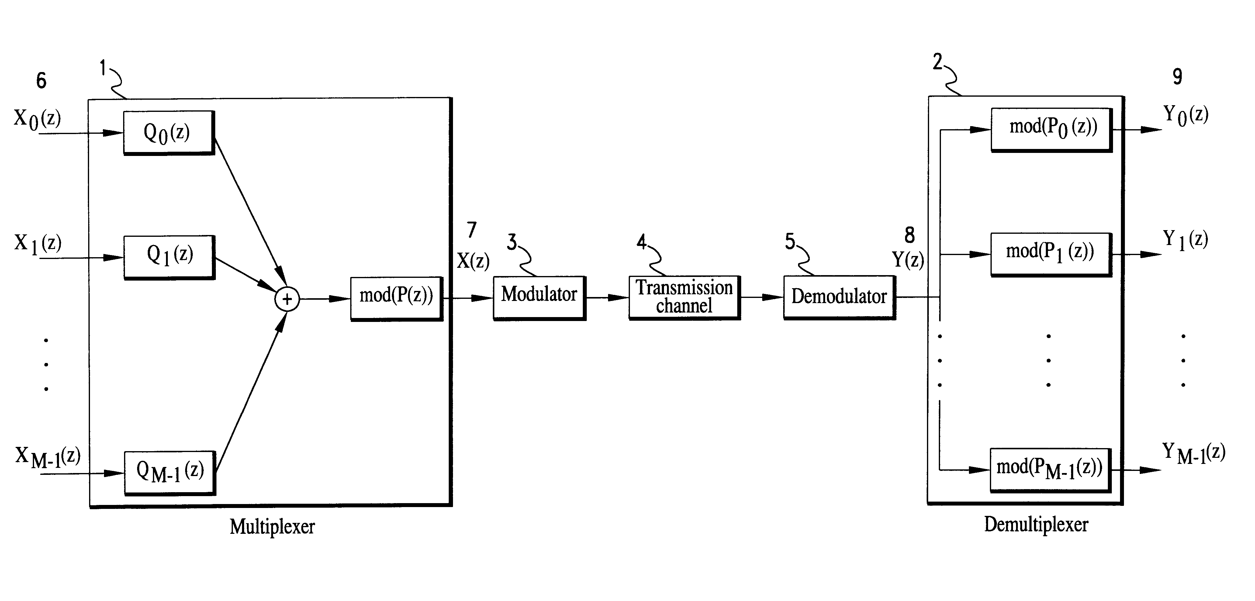
The form of (7) is basically the same as that of the equation (6) for the linear filter with additive noise channel, and therefore the conventional techniques for such a channel are readily applied to subchannel communications.
(a) The multiplexing system multiplexes M subchannel signals of length K into a single signal of length MK, and thus does not have any multiplexing loss. In other words, this multiplexing system fully utilizes the available transmission bandwidth of the channel.
(c) For the linearly distorted transmission channel, the virtual subchannel transmission model has basically the same form as the linearly distorted communication model so that the conventional techniques of the linear transmission channel can be easily applied to the subchannel transmissions.

Problems solved by technology

If code sequences in use are maintained in secrecy, unauthorized listeners cannot extract the subchannel signals' components.
The TDM suffers from interchannel interference if there is a linear distortion in the channel.
In contrast, the FDM raises a problem that transmission bandwidth cannot be efficiently used though interchannel interference rarely occurs due to such a linear distortion.
However, when there is a linear distortion in the transmission channel, the orthogonal property may not hold, and it generally causes interchannel interference.

Method used


Image

  • Residue division multiplexing system and apparatus for discrete-time signals
  • Residue division multiplexing system and apparatus for discrete-time signals
  • Residue division multiplexing system and apparatus for discrete-time signals

Examples


first embodiment

In this embodiment, both the subchannel signals and the multiplexed signal take complex values. The complex multiplexed signal can be transmitted via the carrier frequency transmission by quadrature amplitude modulation (QAM). The QAM process modulates the in-phase and quadrature components of the carrier by the real and imaginary parts of the complex multiplexed signal, independently. Assuming that this modulation scheme is used for transmission, the multiplexing system for complex signals is implemented. The multiplexer 1 and the demultiplexer 2 are shown to be implemented efficiently for the appropriate choices of P.sub.m (z), m=0, 1, . . . , M-1.

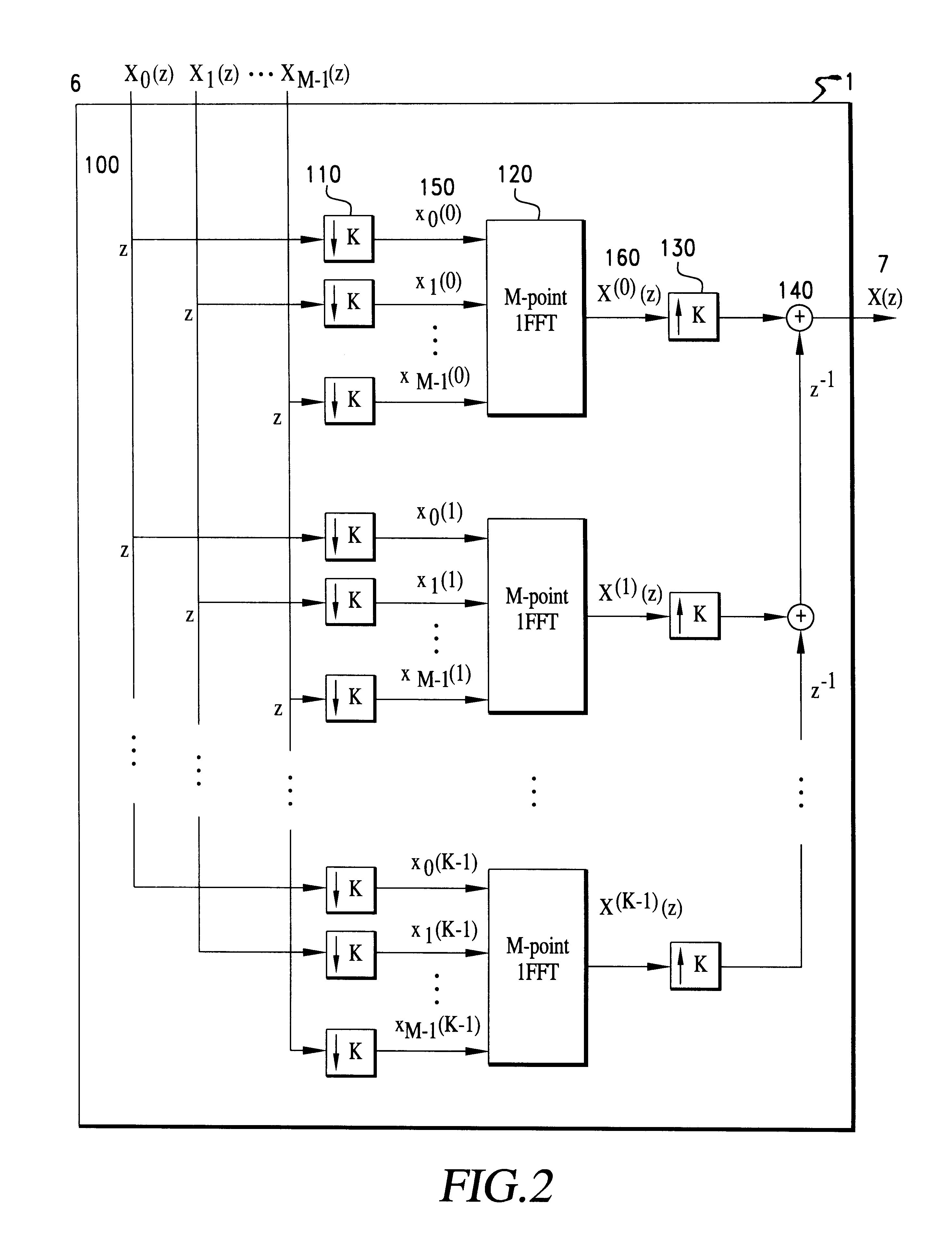
FIG. 2 shows a block diagram of the multiplexer 1 suitable for complex signals in which the number of subchannels is M, and the length of the subchannel signals is K. Each of the subchannel signal polynomials is first divided into its coefficients, which are then fed to the inputs of an IFFT (Inverse Fast Fourier Transform) processor 120...

second embodiment

In many cases, signals such as speech and images are quantized to take only specified values. For these signals, the subchannel signals can be represented as integer-valued sequences with a finite range. In the following description, the multiplexing system of the first embodiment is modified here for multiplexing such integer-valued subchannel signals.

Number theoretic transform is known as a transform method for integer-valued signals of a finite range. Let q be a positive integer, and R(q) denote the integer residue ring on mod(q). Elements of R(q) are generally represented as integers, 0, 1, . . . , q-1, and the addition and multiplication of the elements are performed by integer residue arithmetic on mod(q). If an element .alpha. in R(q) satisfies

.alpha..sup.n.ident.1 mod(q) (16)

and if .alpha..sup.x is not unity for any positive integer x of less than N, then .alpha. is referred to as a primitive Nth root of unity in R(q). Since all the arithmetics are integer residue arithmetic...

third embodiment

For digital communication, signals are generally represented as sequences of binary digits 0 and 1. In this embodiment, the multiplexing system of the first embodiment is modified to be suitable for such binary subchannel signals.

For a prime integer q and a positive integer r, it is possible to build a finite field of q.sup.r elements, which is generally referred to as a Galois field denoted as GF(q.sup.r). GF(q.sup.r) is represented in r-dimensional vector form as

GF(q.sup.r)={(x.sub.1 x.sub.2 . . . x.sub.r).vertline.x.sub.i.epsilon.GF(q)} (21)

The elements of GF(2) are 0 and 1 so that elements of GF(2.sup.r) are represented as r-dimensional vectors with 0 and 1, and such sequences are suitable for coded signals or computer communication.

This multiplexing system is implemented by using GF(q.sup.r) in place of R(q) in the second embodiment. There exists a primitive Mth root of unity in GF(q.sup.r) if M divides q.sup.r -1. Using such a primitive root of unity, the M-point transform and...


PUM


Abstract

A multiplexing system utilizes the whole transmission bandwidth without inducing interchannel interference for a linear channel with additive noise. Using the multiplexing system, the linear distortion channel is decomposed into independent linear distortion subchannels. Treating z-transforms as polynomials, a multiplexer at a receiver utilizes the Chinese remainder procedure to combine subchannel signals into a multiplexed signal to be transmitted through a single transmission channel. A demultiplexer at a receiver recovers the transmitted subchannel signals by taking residue polynomials on the factor polynomials used in the Chinese remainder procedure. The multiplexer that combines M subchannel signals of length K may be implemented by K M-point IFFT processors using 1-ej2pim / Mz-K (m=0 to M-1) as relatively prime polynomials required in the Chinese remainder procedure. Samples from the subchannel signals are arranged in K groups of M samples such that each group contains samples at the same position in the subchannel signals, M-point inverse DFTs of the arranged samples are computed for all of the groups, and finally the multiplexed signal is obtained by performing polyphase composition of the inverse DFT outputs. Reversing the process of multiplexing, the demultiplexer is implemented by K M-point FFT processors. Another class of the system is a multiplexing system using (1-ej2pim / Mr0z-1) (1-ej2pim / Mr1z-1) . . . (1-ej2pim / MrK-1z-1) (m=0 to M-1) as relatively prime polynomials, wherein ri is a non-zero complex number (i=0 to K-1). The multiplexer obtains the multiplexed signal by applying the Chinese remainder procedure recursively, starting with the subchannel signals Xm(z) regarding them as residue polynomials on mod((1-ej2pim / Mr0z-1) (1-ej2pim / Mr1z-1) . . . (1-ej2pim / MrK-1z-1)) (m=0 to M-1).

Description

1. Field of the InventionThis invention relates to a multiplexing system and multiplexing and demultiplexing apparatuses for telecommunication, capable of transmitting a number of parallel signals (hereinafter referred to as subchannel signals) through a single transmission channel. The multiplexing system, more particularly, includes the multiplexing apparatus that converts subchannel signals into a single signal (hereinafter referred to as a multiplexed signal) at a transmitter, and a demultiplexing apparatus that recovers the subchannel signals from the received multiplexed signal at a receiver.2. Description of Related ArtFrequency division multiplexing (FDM) and time division multiplexing (TDM) represent conventional primary multiplexing techniques for dividing a single transmission channel into a number of virtual subchannels. The TDM is a multiplexing system that assigns samples of subchannel signals into nonoverlapping time slots. The FDM, on the other hand, achieves the mul...

Claims


Application Information

Patent Timeline
Patent Type & Authority Patents(United States)
IPC IPC(8): H04J13/02H04L5/02H04J11/00H04J13/00H04J99/00
CPCH04J13/00H04L5/02
Inventor MURAKAMI, HIDEO
Owner MURAKAMI HIDEO
Learn More