
Nitrogen oxide sensor

a technology of nitrogen oxide and sensor, which is applied in the direction of instruments, electrolysis components, material analysis, etc., can solve the problems of difficult practical purposes, and inability to detect nox concentration in an environment to be measured

Inactive Publication Date: 2001-11-20
RIKEN CO LTD
View PDF13 Cites 42 Cited by
  • Summary
  • Abstract
  • Description
  • Claims
  • Application Information

AI Technical Summary

Benefits of technology

The present invention has an object to provide a nitrogen oxide converting device which has a higher nitrogen oxide converting ability free from being deteriorated even when the power is ON, and a nitrogen oxide sensor which has a high and stable sensor output by combining the converting device with the electromotive force type or mixed potential type nitrogen oxide sensor.
There is further provided a nitrogen oxide converting electrode of platinum and ruthenium, which is given a high activity to the nitrogen oxide and stable even when energized, by optimizing the composition and mode of the converting electrode and by adding a third element of precious metal.

Problems solved by technology

Since the sensitivities of the electrodes to NO and NO.sub.2 are different, however, the NOx concentration cannot be detected in an environment to be measured where the two gases (NO and NO.sub.2) coexist, or the concentration of neither NO nor NO.sub.2 can be detected.
Moreover, these sensors are troubled by their moisture and heat resistances because they employ a nitrate in the auxiliary electrode, so that they are substantially difficult for the practical purposes from the standpoint of long-term stability.
However, this sensor is also different in the sensitivity to NO and NO.sub.2 so that it cannot detect the NOx concentration in an environment to be measured where the two gases coexist.
When the concentration of the gas to be detected is low, the interference of the residual oxygen concentration in the measured environment is high, and the signal current is minute.
In a noisy circumstance as in an automobile, the S / N ratio is so poor that the NOx concentration is difficult to detect accurately.
However, these constructions are excellent in sensitivity to NO or NO.sub.2 but are troubled by the mutual interference of NO or NO.sub.2 or by the interference of a reducing gas.
Since the oxygen concentration is controlled by the oxygen pump, it is difficult to make a conversion into the single NO gas or the single NO.sub.2 gas, and the mutual interference cannot be sufficiently avoided.
At a low temperature of lower than 400.degree. C., specifically, the ion conductivity of the solid electrolyte body itself is so poor as to make it difficult to detect a stable output.

Method used


Image

  • Nitrogen oxide sensor
  • Nitrogen oxide sensor
  • Nitrogen oxide sensor

Examples


example 2

(Example 2)

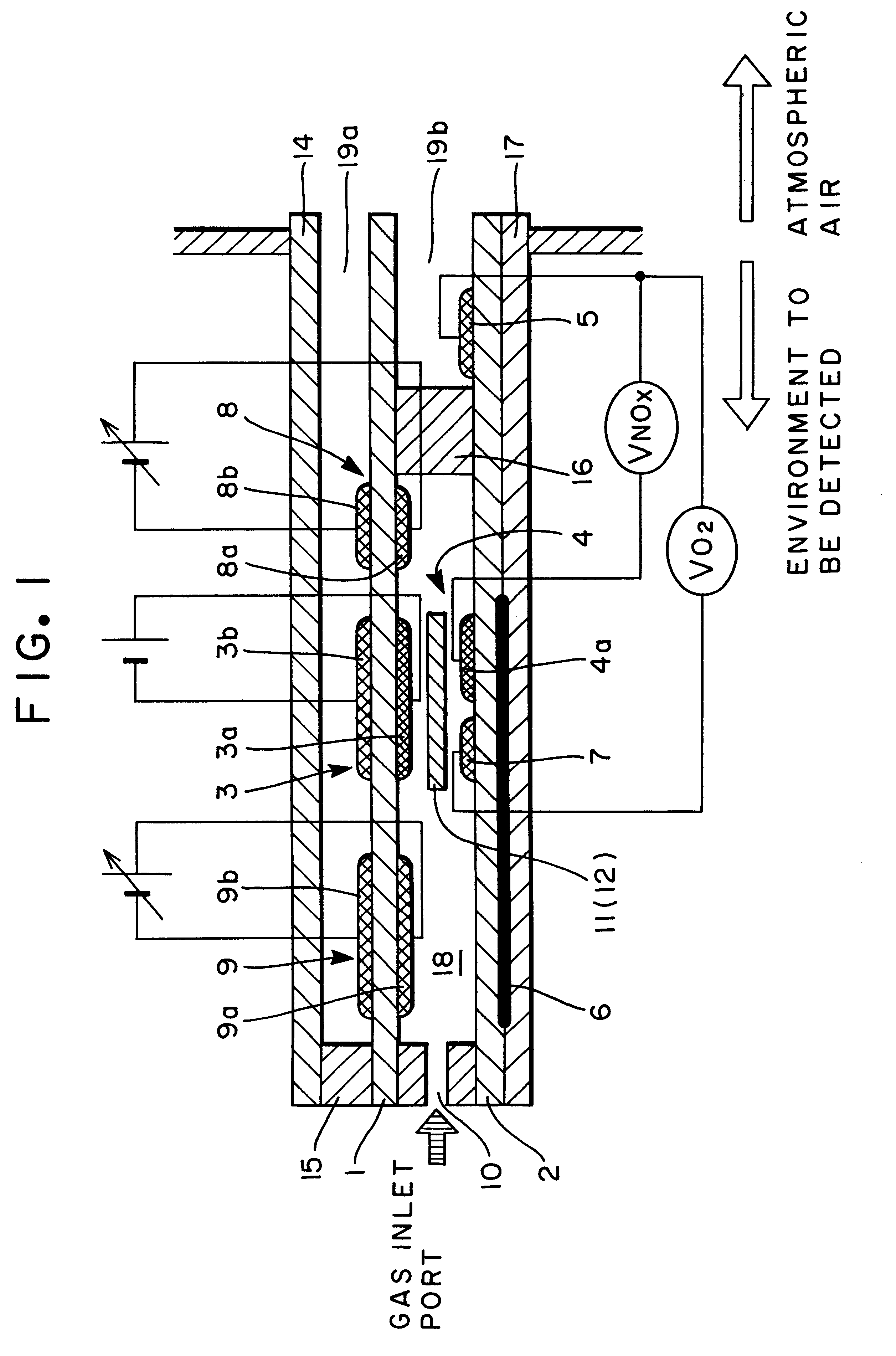
In the construction, the nitrogen oxide sensor, as constructed to include the oxygen pumping portion, the auxiliary oxygen pumping portion, the preliminary oxygen pumping portion, the NOx gas detecting portion and the oxygen sensor portion, was made. The materials, qualities, sizes and baking conditions for making the individual portions other than the preliminary oxygen pumping portion were identical to those of Example 1. The preliminary oxygen pumping portion was formed on the green sheet, on which the oxygen pumping portion was made, and upstream of the oxygen pumping portion. Both the electrodes in the gas chamber and the electrodes in the ambient duct were formed by applying the Pt paste by the screen printing method.

The sensor thus made was examined on its outputs by keeping it at 600.degree. C. with the buried heater and by placing it in the simulation gas having a known composition. The preliminary oxygen pumping portion was so driven with an applied voltage of 0...

example 3

(Example 3)

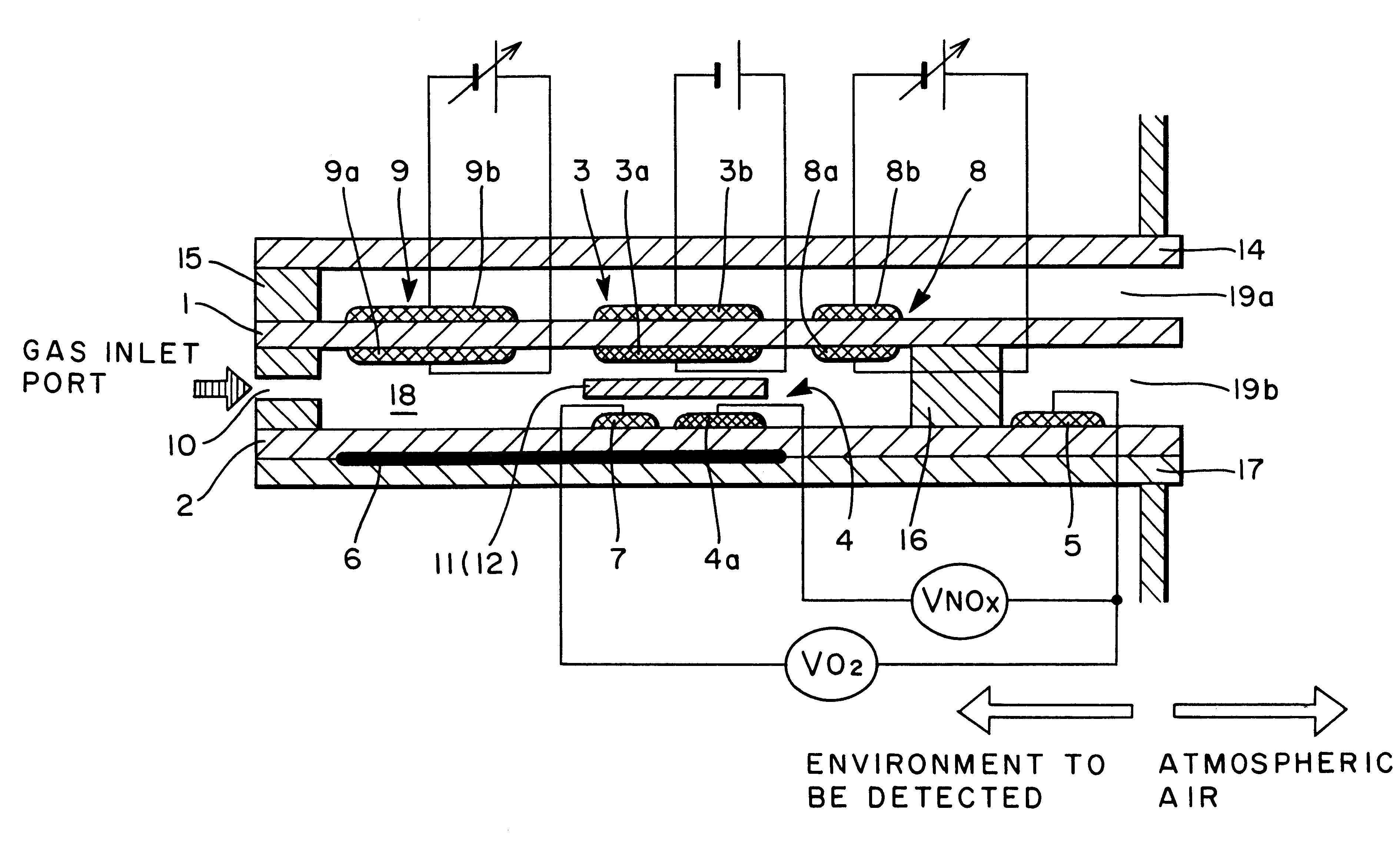
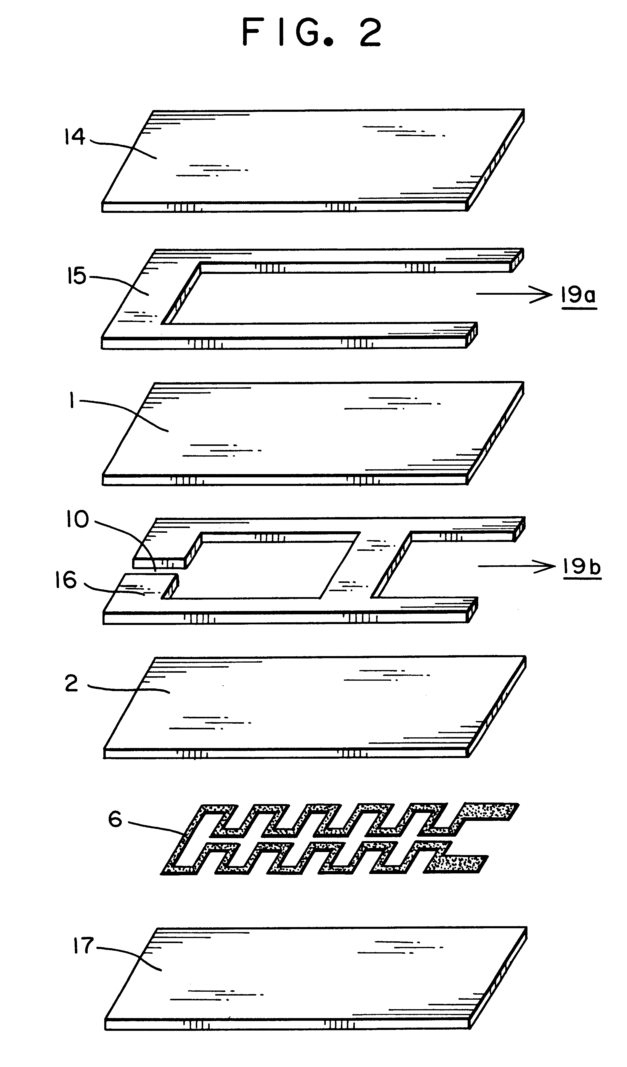
In the construction of FIG. 1, the nitrogen oxide sensor, as constructed to include the oxygen pumping portion, the auxiliary oxygen pumping portion, the NOx gas detecting portion, the oxygen sensor portion and the porous member, was made. The gas chamber partitioning green sheet for constructing the gas chamber was given a thickness of 40 .mu.m, and the oxygen pumping electrode and the NOx detecting electrode in the gas chamber were made to contact each other through a porous alumina film. Also made was a sensor in which the oxygen pumping electrode and the NOx detecting electrode in the gas chamber were in contact through a porous film containing alumina carrying palladium. The materials, qualities, sizes and baking conditions for making the oxygen pumping portion, the auxiliary oxygen pumping portion, the NOx gas detecting portion and the oxygen sensor portion were identical to those of Example 1. The counter electrode was formed in the ambient duct, and the counter el...

example 4

(Example 4)

In the construction of FIG. 1, the nitrogen oxide sensor, as constructed to include the oxygen pumping portion, the auxiliary oxygen pumping portion, the NOx gas detecting portion, the oxygen sensor portion and the porous member, was made. The gas chamber partitioning green sheet for constructing the gas chamber was given a thickness of 40 .mu.m, and the oxygen pumping electrodes and the NOx detecting electrodes in the gas chamber were made to contact with each other through the porous alumina film. The materials, qualities, sizes and backing conditions for making the auxiliary oxygen pumping portion, the NOx gas detecting portion and the oxygen sensor portion were identical to those of Embodiment 1. The counter electrode was formed in the ambient duct, and the counter electrode of the oxygen sensor was shared. The oxygen pumping portion had the NOx converting electrode made of a material, as tabulated in Table 3, the pumping electrode made of platinum, and the size and b...


PUM

PropertyMeasurementUnit
voltageaaaaaaaaaa
diameteraaaaaaaaaa
temperatureaaaaaaaaaa

Abstract

A nitrogen oxide sensor enabled to enhance the measurement concentration of a total of nitrogen oxides by oxidizing or reducing the nitrogen oxides on the surfaces of electrodes in addition to the control of an oxygen concentration by an oxygen pump. An electrode (3a) in a gas chamber (18) constructing an oxygen pumping portion (3) is made of a material (e.g., Pt-3 wt % Rh) having a function to oxidize a nitrogen oxide gas.

Description

1. Field of the InventionThe present invention relates to a nitrogen oxide sensor for detecting a concentration of a nitrogen oxide. More particularly, the invention relates to a nitrogen oxide device for converting NO into NO.sub.2 or NO.sub.2 into NO electrochemically.2. Prior ArtA solid element type of nitrogen oxide sensor has been representatively disclosed in the Japanese Patent Laid-Open Publication No. Hei 4-142455 (1983). This sensor is equipped on an ion conductor with a nitrate electrode and a reference electrode to measure an electromotive force to be generated between the electrodes, so that it has sensitivity to NO and NO.sub.2. Since the sensitivities of the electrodes to NO and NO.sub.2 are different, however, the NOx concentration cannot be detected in an environment to be measured where the two gases (NO and NO.sub.2) coexist, or the concentration of neither NO nor NO.sub.2 can be detected.In order to improve the sensitivities to NO and NO.sub.2, there has been pro...

Claims


Application Information

Patent Timeline
Patent Type & Authority Patents(United States)
IPC IPC(8): G01N27/417G01N33/00G01N27/416G01N27/419
CPCG01N27/417G01N33/0037Y02A50/20
Inventor HASEI, MASAHARUYAN, YONGTIEGAO, YUNZHIONO, TAKASHIKUNIMOTO, AKIRA
Owner RIKEN CO LTD
Learn More