
Thermal buffering of cross-coils in high-power NMR decoupling

a cross-coil and nmr decoupling technology, applied in the field of high-power nmr decoupling, can solve the problems of inability to achieve this level of proton decoupling above 200 mhz in prior art coils and circuits, difficult to affix a coil like this to the inside of the coil, etc., and achieve the effect of high thermal conductivity

Inactive Publication Date: 2001-11-20
DOTY SCI
View PDF10 Cites 52 Cited by
  • Summary
  • Abstract
  • Description
  • Claims
  • Application Information

AI Technical Summary

Benefits of technology

A transverse rf foil saddle coil for use in NMR is affixed in intimate thermal contact on one surface of a ceramic cylindrical coilform of high thermal conductivity--often for solid samples at high fields where the axis of the coilform is not aligned with B.sub.0. An orthogonal rf coil is mounted in intimate thermal contact to the first saddle coil via a ceramic spacer or coilform. The coilform is cooled by high-velocity gas flow--often also associated with bearing ex...

Problems solved by technology

However, prior art coils and circuits are not capable of this level of proton decoupling above 200 MHz unless major sacrifices (factors of 2 to 4) are made in MF and LF sensitivity.
However, such prior art attempts have not been satisfactory because solids NMR at high fields is generally applied to sample sizes below 6 mm, where it is critical that spacing between coils be minimized to maintain acceptable .eta..sub.F on the outer coil.
Moreover, it is very difficult to affix a coil like this to the inside of a coil former in a way that achieves both high B.sub.1 and B.sub.0 homogeneity.

Method used


Image

  • Thermal buffering of cross-coils in high-power NMR decoupling
  • Thermal buffering of cross-coils in high-power NMR decoupling
  • Thermal buffering of cross-coils in high-power NMR decoupling

Examples


Embodiment Construction

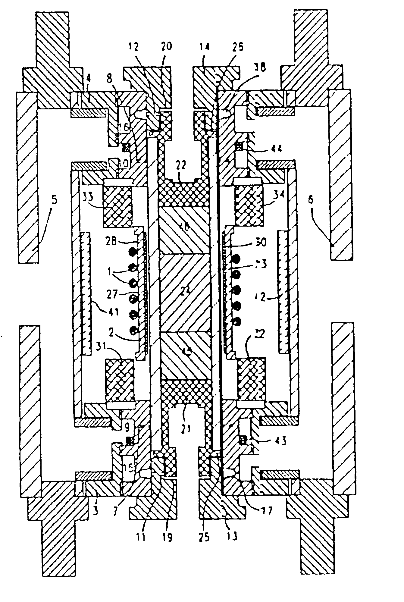
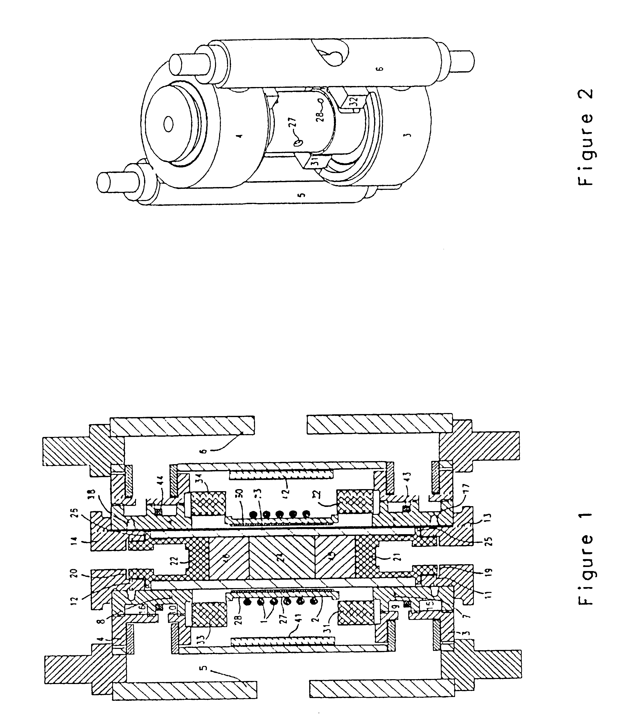
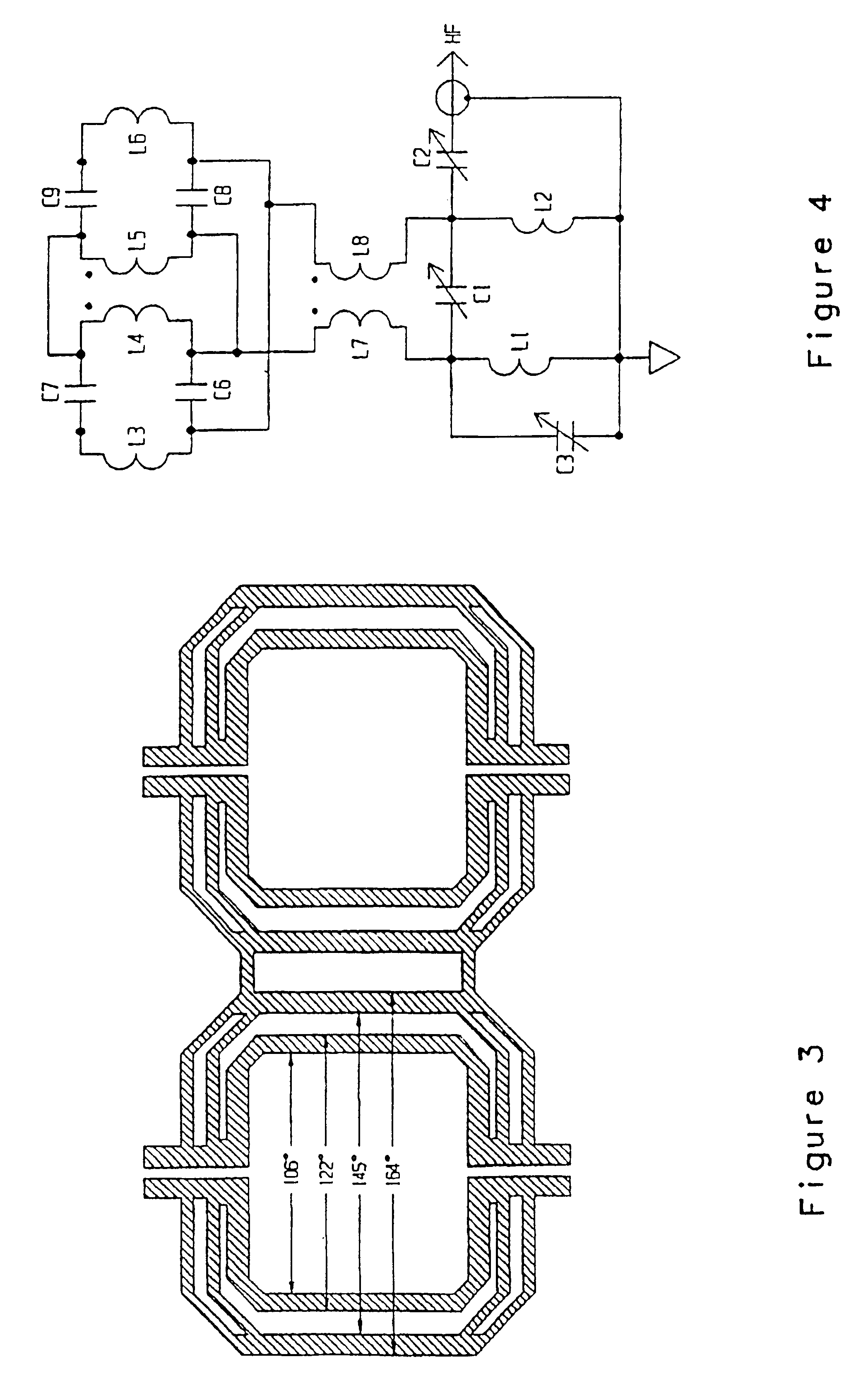
The manifolding modifications of the MAS spinner disclosed in FIGS. 1 and 2 permit improved access to the coil region, as required for practical manufacturing when two rf coils are used. Prior art supersonic NMR sample spinners similar to that of U.S. Pat. No. 5,508,615 have often been furnished with a solenoidal rf coil 1 on the outside (rather than inside, as shown in that patent) of the ceramic coilform 2 to simplify manufacturing, but the continuous (full-length) outer sleeve arrangement of the prior art is impractical when two coils are required. Separate manifolding sleeves 3, 4 at each end may be supplied with bearing gas through a bearing tube 5 on one side, and drive gas may be supplied through a drive tube 6 on the other side, leaving the central coil region readily accessible. To facilitate variable temperature operation and to improve magnetic homogeneity, a clamshell (split-cylinder) cover 41, 42 (not shown in FIG. 2) with suitable lead holes may be removably affixed ar...


PUM


Abstract

A transverse rf saddle coil (30) for use in NMR is affixed in intimate thermal conract on one surface of a ceramic coilform (23) of high thermal conductivity. The probe is mostly for use with solid samples at high fields where the axis of the coilform is not alignedwith the main field. An orthogonal rf coil (1) is mounted in intimate thermal contact to the first saddle coil (30) via a ceramic spacer or coilform (2). The coilform is cooled by high-velocity gas flow and is also often associated with bearing exhaust gas from a high speed sample spinner. The two coils are tuned to different rf frequencies with circuits capable of supporting high rf currents. The rf coils (30, 1) may be magnetically compensated and expansion controlled, and passive geometric compensation of magnetic susceptibility effects from a sample spinner stator may also be incorporated. Novel coil mounting techniques, including metallurgical bonds to ceramics and capturing by dielectric clam-shells, are also disclosed.

Description

The field of this invention is the measurement of nuclear magnetic resonance (NMR) for the purpose of determining molecular or microscopic structure, and, more particularly, a novel coil arrangement for NMR measurements of samples requiring simultaneous high-power excitation at more than one frequency.There have been numerous applications for double and triple resonance circuits in NMR of solid samples with high-power decoupling for the past three decades. The most common application is irradiating at the proton (.sup.1 H) high frequency (HF) resonance to decouple its dipolar broadening effects while observing Bloch decays on a nuclide of lower magnetogyric ratio such as .sup.13 C at a low frequency (LF). Other common examples of multiple resonance circuits include cross-polarization (CP) and Rotational Echo Double Resonance (REDOR). A number of specialized techniques--Dynamic Angle Spinning (DAS), Double Rotation (DOR), single-crystal, etc.) have been developed during the past deca...

Claims


Application Information

Patent Timeline
IPC IPC(8): G01R33/34G01R33/36
CPCG01R33/34053G01R33/34069G01R33/3635G01R33/34007G01R33/34092
Inventor DOTY, DAVID F.ENTZMINGER, JR., GEORGE
Owner DOTY SCI
Learn More