

Disk labeling devices
a labeling device and disk technology, applied in the direction of identification means, instruments, manufacturing tools, etc., can solve the problems of inability to achieve the effect of achieving dynamic balance, inability to achieve labeling in printing or painting, and inability to determine the contents of disks
- Summary
- Abstract
- Description
- Claims
- Application Information
AI Technical Summary
Benefits of technology
Problems solved by technology
Method used
Image

Examples
example 2
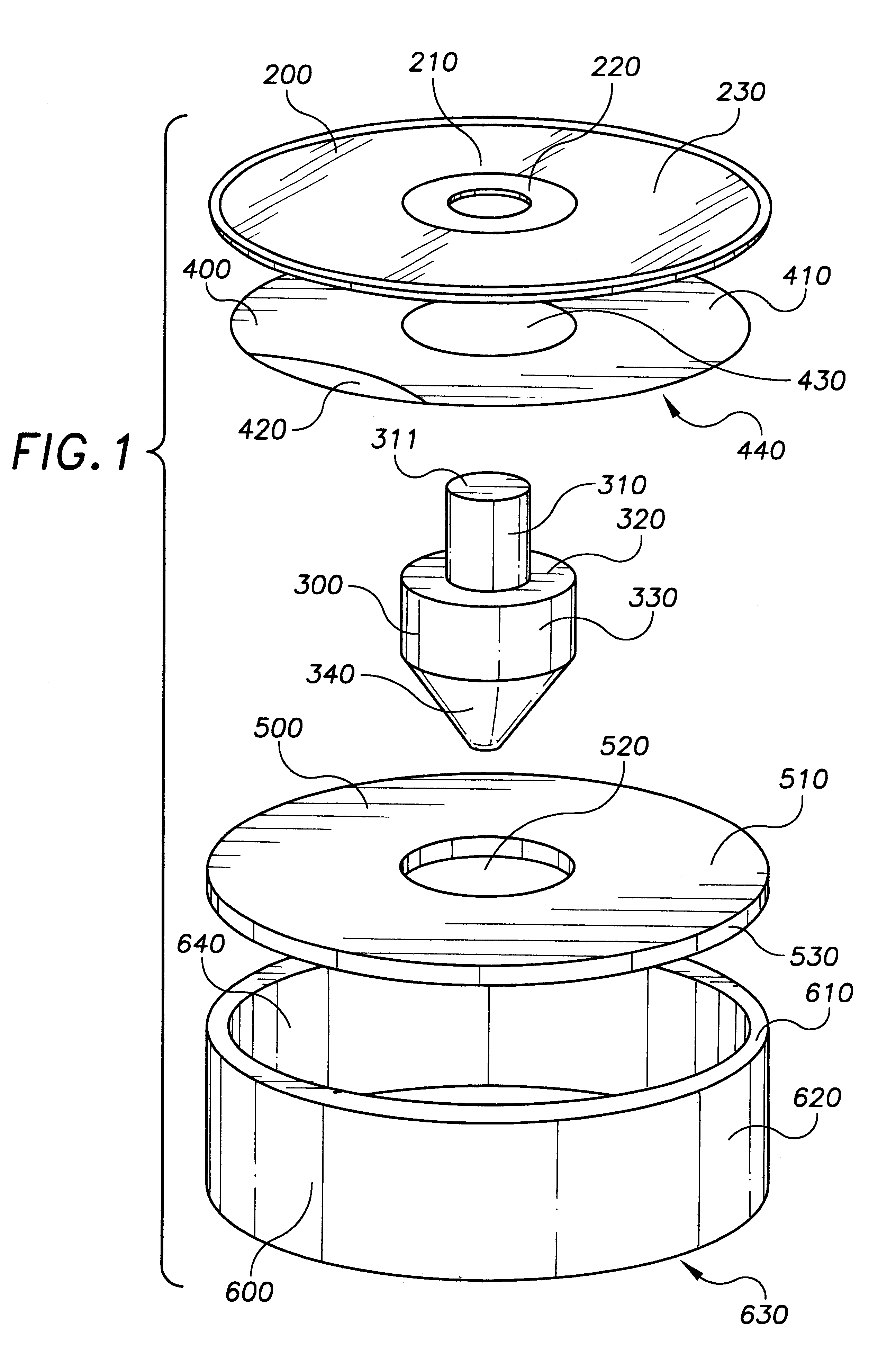
In use, the positioning plate 500 is provided on top of cylindrical base 600, with the positioning plate 500 in contact with flat lip member 610, preferably affixed thereto. The flat bottom 630 is supported by an external surface, such as a table top or other desired flat surface. Then, the self-adhesive label 400 is placed onto surface area 510 of positioning plate 500, with adhesive side 420 facing up and away from positioning plate 500. Self-adhesive label 400 is placed on positioning plate 500 in a manner which positions self-adhesive label 400 so that hole area 430 is overlapping the positioning hole 520. As such, an observer should be able to see through self-adhesive label 400 and positioning plate 500 and into cylindrical base 600. Then compact disk 200 is placed onto positioning cone 300 by placing elongated stock 310 through center hole 210, so that center area 220 of compact disk 200 is resting upon flat surface 320. The compact disk 200 on the cylindrical extension 310 i...
example 3
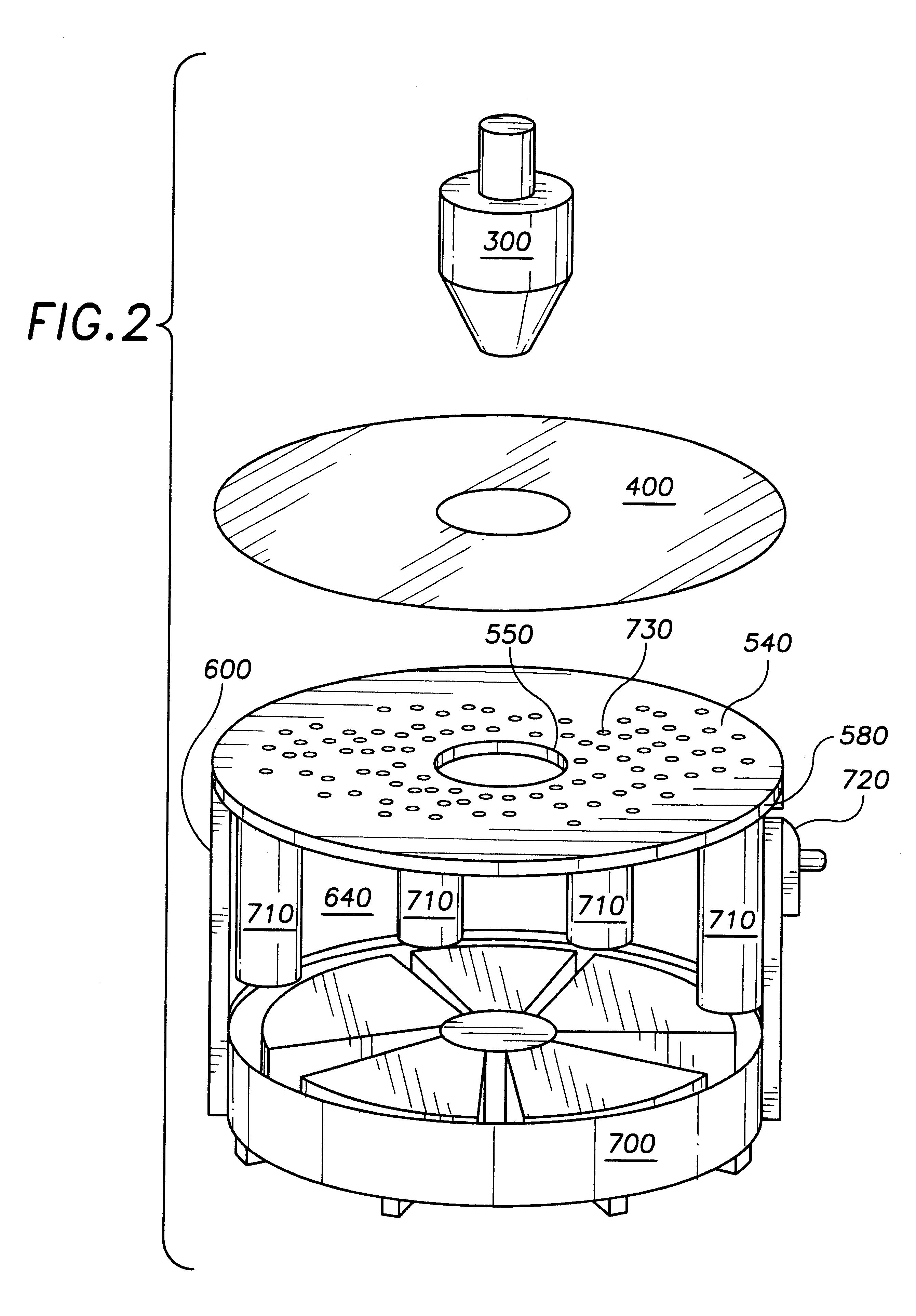
Referring now to FIG. 3, a labeler is provided generally in accordance with the embodiments of Examples 1 and 2. The positioning plate 500 has a plurality of evenly spaced small holes 540, e.g., 0.5 mm diameter holes in a hexagonal array on 1.0 centimeter centers. A 6 volt muffin type fan 700 is provided in the base 600, which exhausts out of the base 600 to draw a partial vacuum in the hollow space 640. Thus, a flow is directed inward through the holes 540, which will draw the label 400 toward the positioning plate 500. The inner edge of the positioning hole is provided with an "O" ring 550 to seal around the positioning cone 300, which has a smooth surface.
The muffin fan 700 is driven by 4 D-type alkaline cells 710, which are arranged inside the base 600. An on-off switch 720 is provided on a side of the base. Alternately, a switch 730, e.g., a Microswitch-type mechanical sensor, may be provided in cooperation with the O-ring 550, which activates the muffin fan 700 when the positi...
example 4
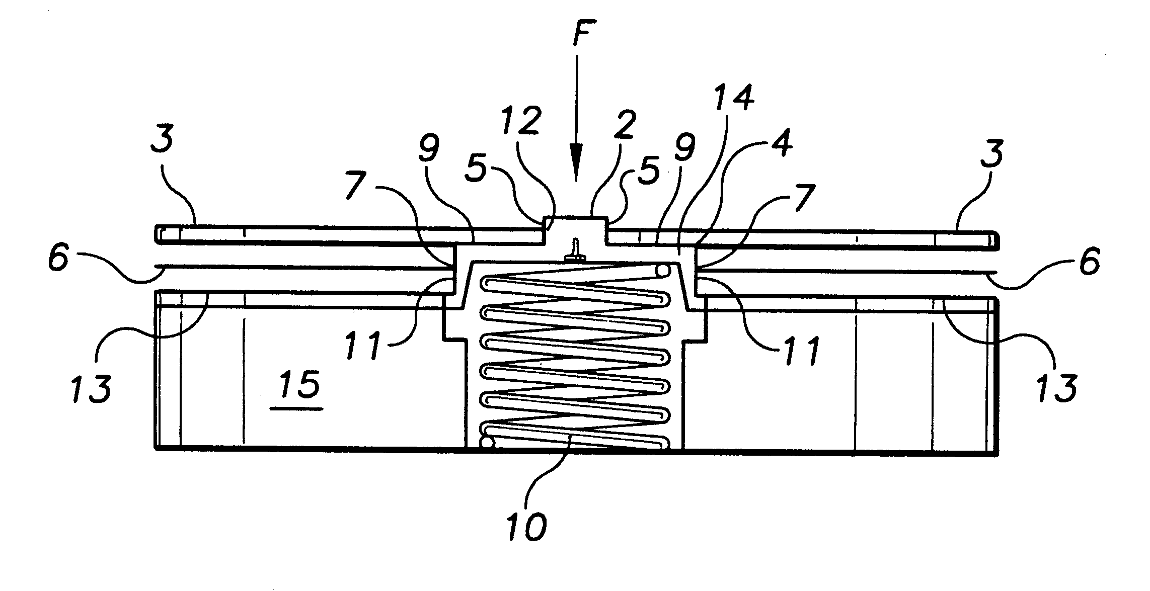
As shown in FIG. 3, an embodiment is provided with the alignment members and base connected. A member for axially aligning the disk 3 and the member for axially aligning the label 6 are affixed to one another. Since the disk 3 spindle aperture 5 is smaller than the label 6 central aperture 7, a coaxial structure 8 having varying characteristic heights is provided, having a first member 11 for axially aligning the label 6, a second member 12 axially aligning the disk 3 having a stop 9. The second member 12 extends upwardly from member 11 for axially aligning the disk 3, and means for selectively contacting the label and the disk after alignment. For example, the contacting means may be a spring 10 loaded cylinder 14 with a central spindle 2 mounted in a plate 13, so that the label 6 is supported by the plate 13 and centered by the cylinder 14; the disk 3 is supported by an upper portion of the cylinder 14 and centered by the spindle 2, and after centering of each, the disk 3 may be l...
PUM
| Property | Measurement | Unit |
|---|---|---|
| distance | aaaaa | aaaaa |
| diameter | aaaaa | aaaaa |
| diameter | aaaaa | aaaaa |
Abstract
Description
Claims
Application Information