Injection apparatus and method of controlling the same

a technology of injection apparatus and injection chamber, which is applied in the direction of liquid transfer device, application, instruments, etc., can solve the problems of deterioration in resin cannot be injected with a sufficiently high injection pressure, and the quality of molded products cannot be maintained

Inactive Publication Date: 2001-11-27
SUMITOMO HEAVY IND LTD
View PDF5 Cites 4 Cited by
  • Summary
  • Abstract
  • Description
  • Claims
  • Application Information

AI Technical Summary

Benefits of technology

Since the frictional resistance acting on resin in the vicinity of the inner circumferential surface of the heating cylinder can be reduced, during the injection step, the injection pressure can be made to correspond to the injection force applied to the screw from its rear end, so that a sufficiently large injection pressure can be generated.
Since a sufficiently large injection pressure can be generated, an injection force can be decreased accordingly. Therefore, the size and cost of the injection apparatus can be reduced. In addition, since the frictional resistance decreases, the quantity of shear-generated heat in resin decreases, so that burning of resin can be prevented.

Problems solved by technology

Incidentally, if the pressure of resin in front of the screw head upon starting of the injection step; i.e., injection pressure, involves variation, sink marks and burrs are formed on molded products, resulting in deterioration in quality of the molded products.
However, the conventional injection apparatus has the following drawbacks.
Therefore, in the injection step, the injection pressure does not correspond to an injection force applied to the screw from its rear end, with the result that the resin cannot be injected with a sufficiently high injection pressure, and the injection pressure varies with the frictional resistance.
As a result, the pressure of resin within a mold; i.e., the mold inner pressure, involves variation, with resultant deterioration in quality of molded products.
As a result, the reference position varies, which lowers the quality of molded products.

Method used


Image

  • Injection apparatus and method of controlling the same
  • Injection apparatus and method of controlling the same
  • Injection apparatus and method of controlling the same

Examples


Embodiment Construction

An embodiment of the present invention will next be described in detail with reference to the drawings.

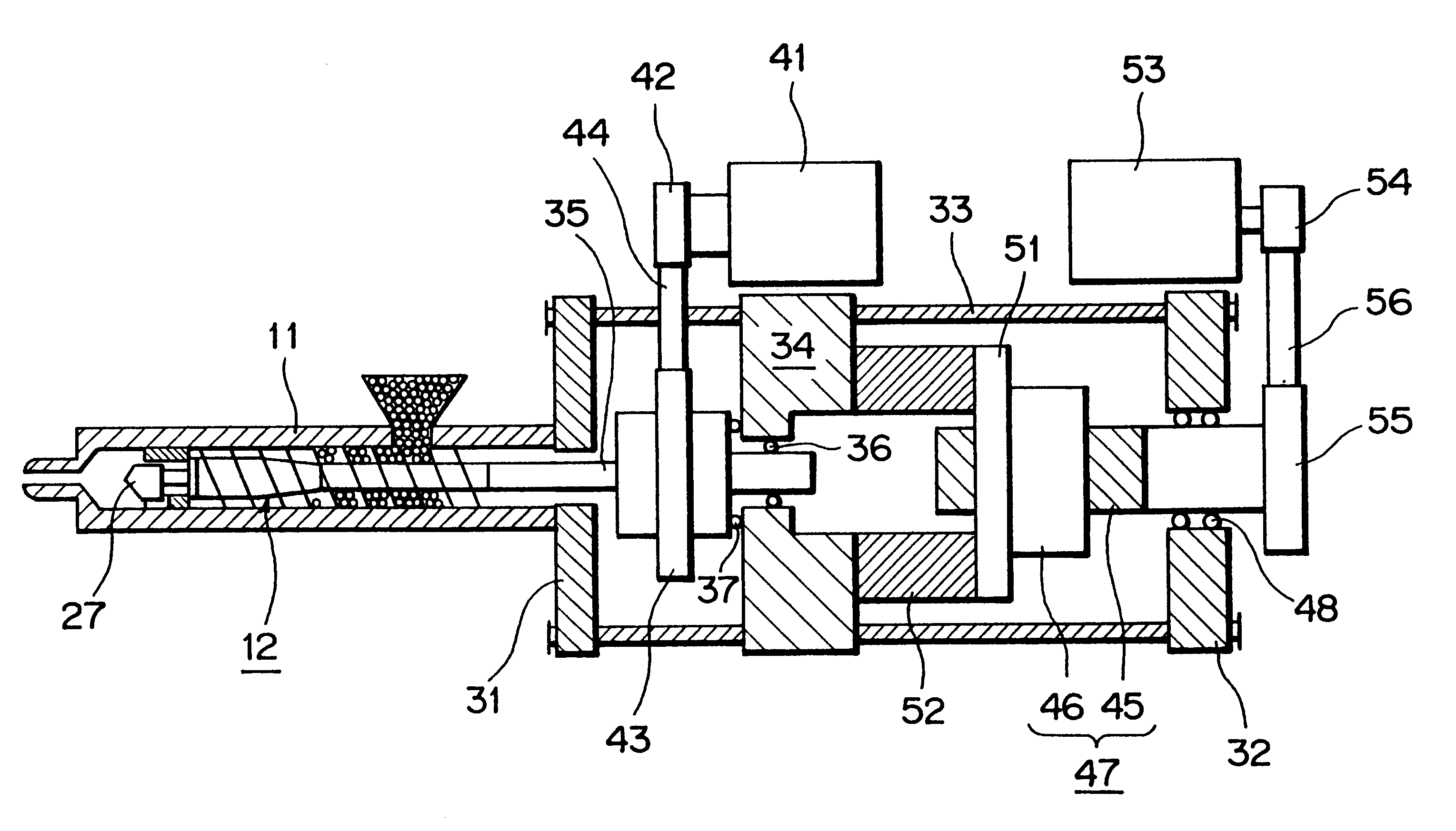
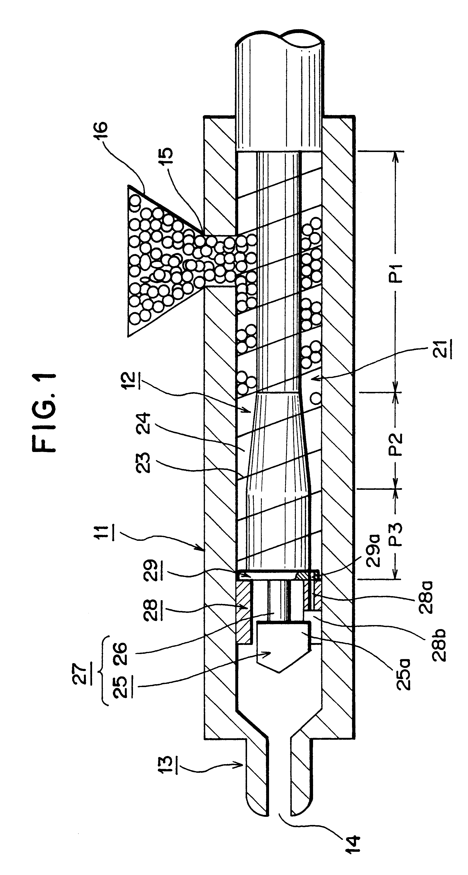
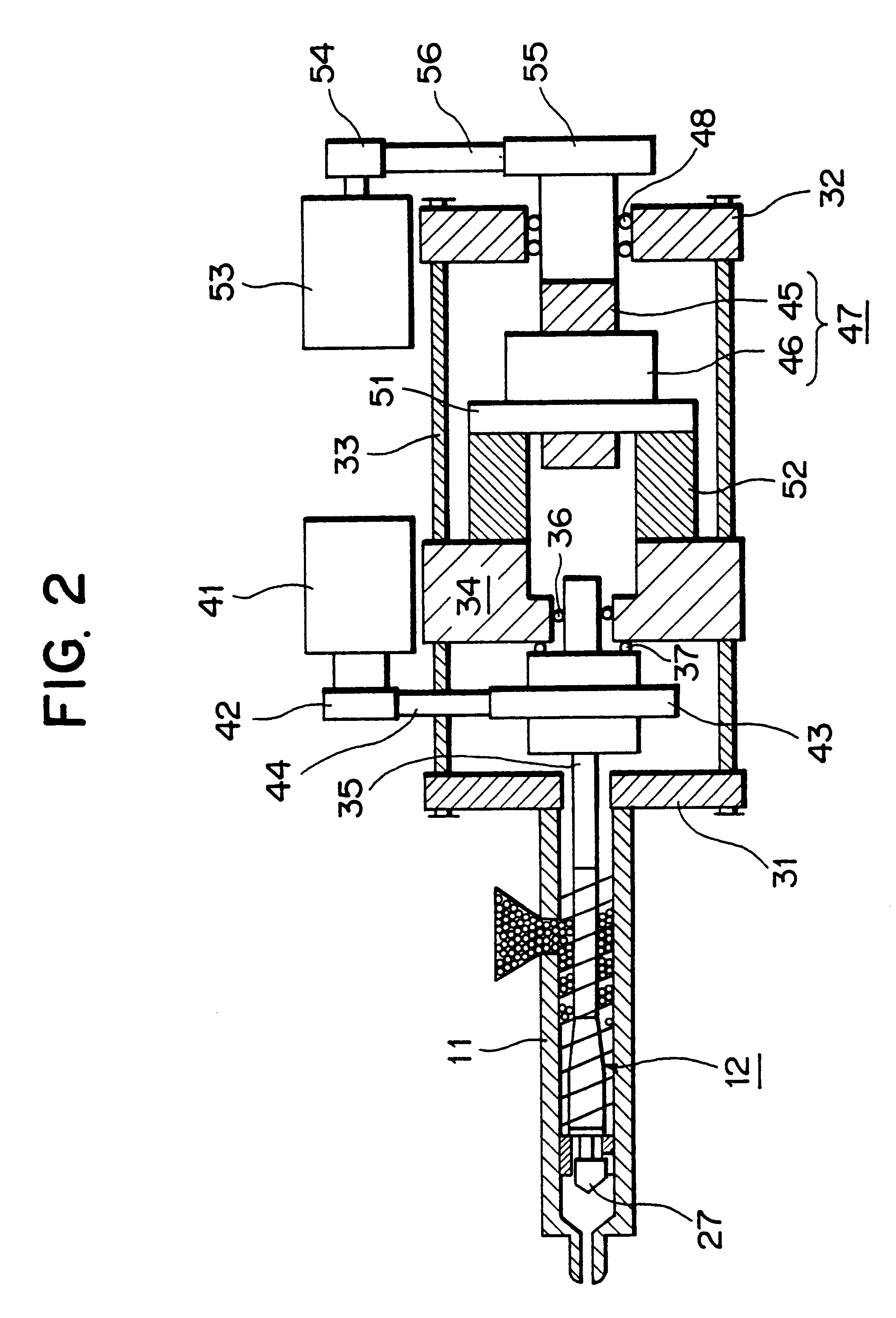
FIG. 1 is an enlarged sectional view of a main portion of an injection apparatus according to an embodiment of the present invention; and FIG. 2 is a schematic view of the injection apparatus according to the embodiment of the present invention.

In FIGS. 1 and 2, reference numeral 11 denotes a heating cylinder serving as a cylinder member; reference numeral 12 denotes a screw which is disposed within the heating cylinder 11 such that the screw 12 can be rotated and can be reciprocated and which serves as an injection member; reference numeral 13 denotes an injection nozzle formed at the front end (the left end in FIG. 1) of the heating cylinder 11; reference numeral 14 denotes a nozzle opening formed in the injection nozzle 13; reference numeral 15 denotes a resin supply port formed in the heating cylinder 11 at a predetermined position in the vicinity of the rear end (the right end...


PUM

PropertyMeasurementUnit
circumferenceaaaaaaaaaa
speedaaaaaaaaaa
flight speedaaaaaaaaaa

Abstract

An injection apparatus which can reduce frictional resistance which acts on resin during an injection step to thereby prevent variation in a reference position and improve quality of molded products. The injection apparatus comprises a heating cylinder; a screw disposed within the heating cylinder to be rotatable and reciprocatable, the screw having a flight portion in which a flight is formed on an outer circumference of a screw body, and a screw head disposed at a front end of the flight portion; a first drive unit for rotating the screw; a second drive unit for advancing and retracting the screw; a screw-advancement control unit for driving the second drive unit in an injection step in order to advance the screw at a predetermined screw speed; and a flight speed control unit for driving the first drive unit in the injection step in order to advance the flight at a flight speed that is apparently lower than the screw speed. Since the frictional resistance acting on resin in the vicinity of the inner circumferential surface of the heating cylinder can be reduced, during the injection step, the injection force can be made to correspond to the injection pressure, so that a sufficiently large injection pressure can be generated.

Description

1. Field of the InventionThe present invention relates to an injection apparatus and a method of controlling the same.2. Description of the Related ArtConventionally, an injection apparatus is disposed in an injection molding machine. A screw is disposed within a heating cylinder of the injection apparatus such that the screw can be rotated and reciprocated by a metering motor and an injection motor. A spiral flight is formed on the outer circumferential surface of the screw, so that a groove is formed by the flight.When the screw is rotated in a forward direction during a metering step, pellets of resin which have fallen from a hopper are melted, and molten resin is caused to advance along the groove. As a result, the molten resin is accumulated on the front side of a screw head, and the screw is retracted accordingly.In order to enable the above-mentioned metering operation, a resin supply section to which pellets of resin are supplied from the hopper, a compression section in whi...

Claims


Application Information

Patent Timeline
Patent Type & Authority Patents(United States)
IPC IPC(8): B29C45/76B29C45/50B29C45/46B29C45/52B29C45/77
CPCB29C45/50B29C45/76B29C45/52B29C2045/1792B29C2945/76006B29C2945/76013B29C2945/76083B29C2945/76113B29C2945/76187B29C2945/76287B29C2945/76381B29C2945/76498B29C2945/76598B29C2945/76665B29C2945/76859B29C2945/76862B29C2945/76943
Inventor IMATOMI, YOSHIYUKIHIRANO, TOMOHIRO
Owner SUMITOMO HEAVY IND LTD
Why Eureka
Try Eureka