
Reversing rotatory shaker movement

a shaker and rotational technology, applied in the direction of mixing, chemistry apparatus and processes, mixers, etc., can solve the problems of poor movement of one element of liquid relative to the other, poor quality of mixing, and inability to solve the underlying problem

Inactive Publication Date: 2001-11-27
BULL DANIEL
View PDF5 Cites 26 Cited by
  • Summary
  • Abstract
  • Description
  • Claims
  • Application Information

AI Technical Summary

Benefits of technology

Another object of this invention is a rotatory shaker movement that produces better mixing at lower inputted energy levels.
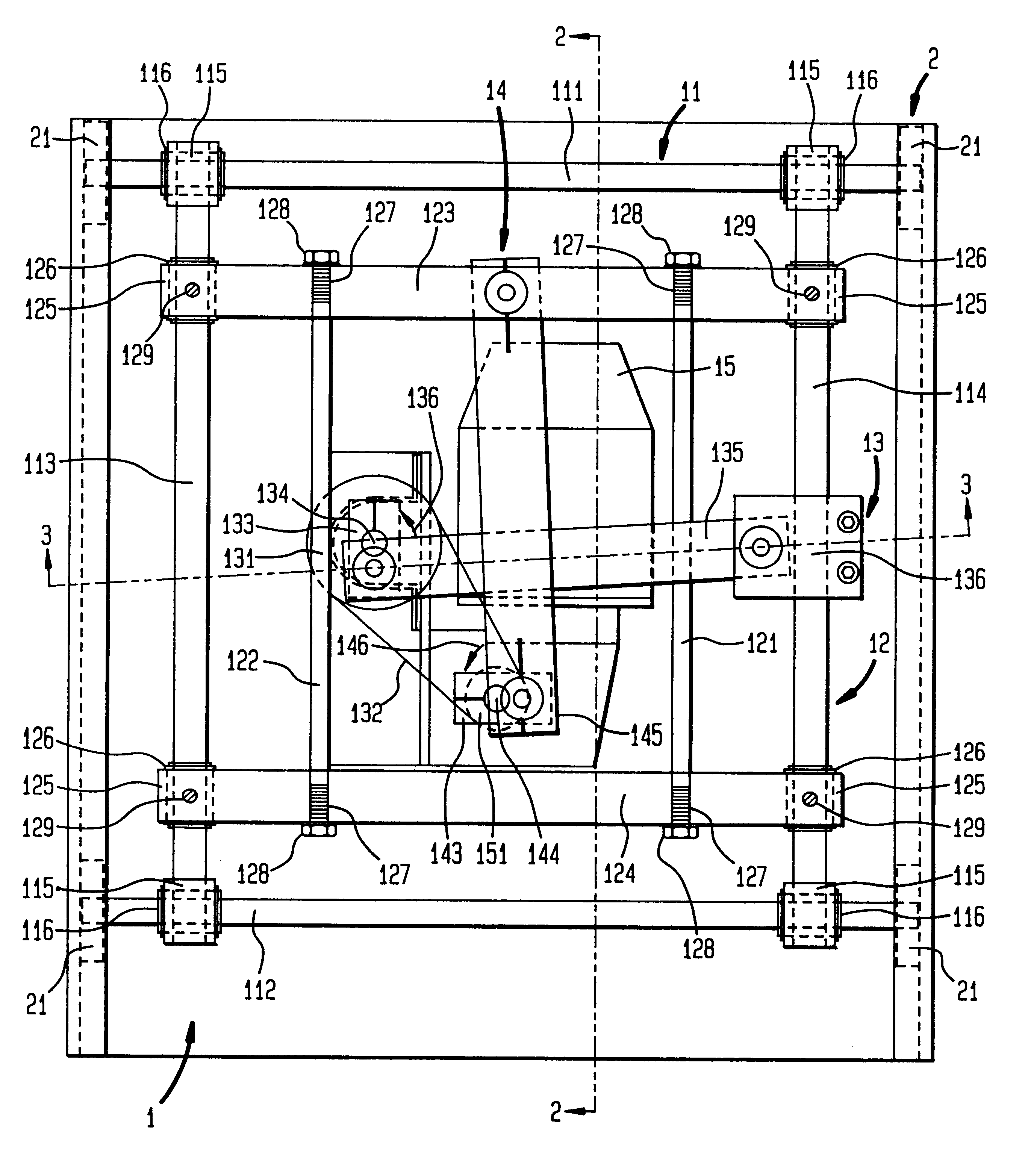
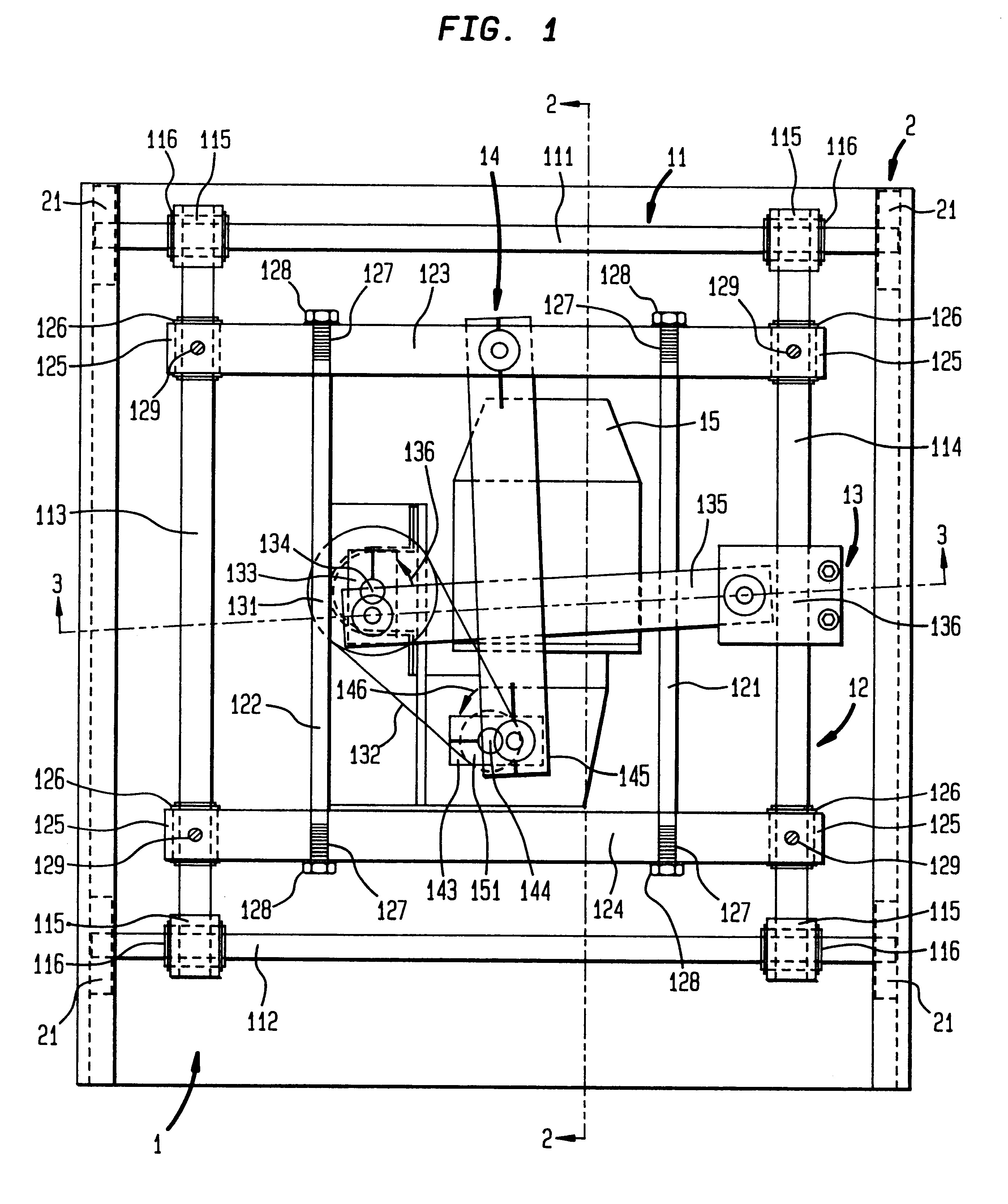
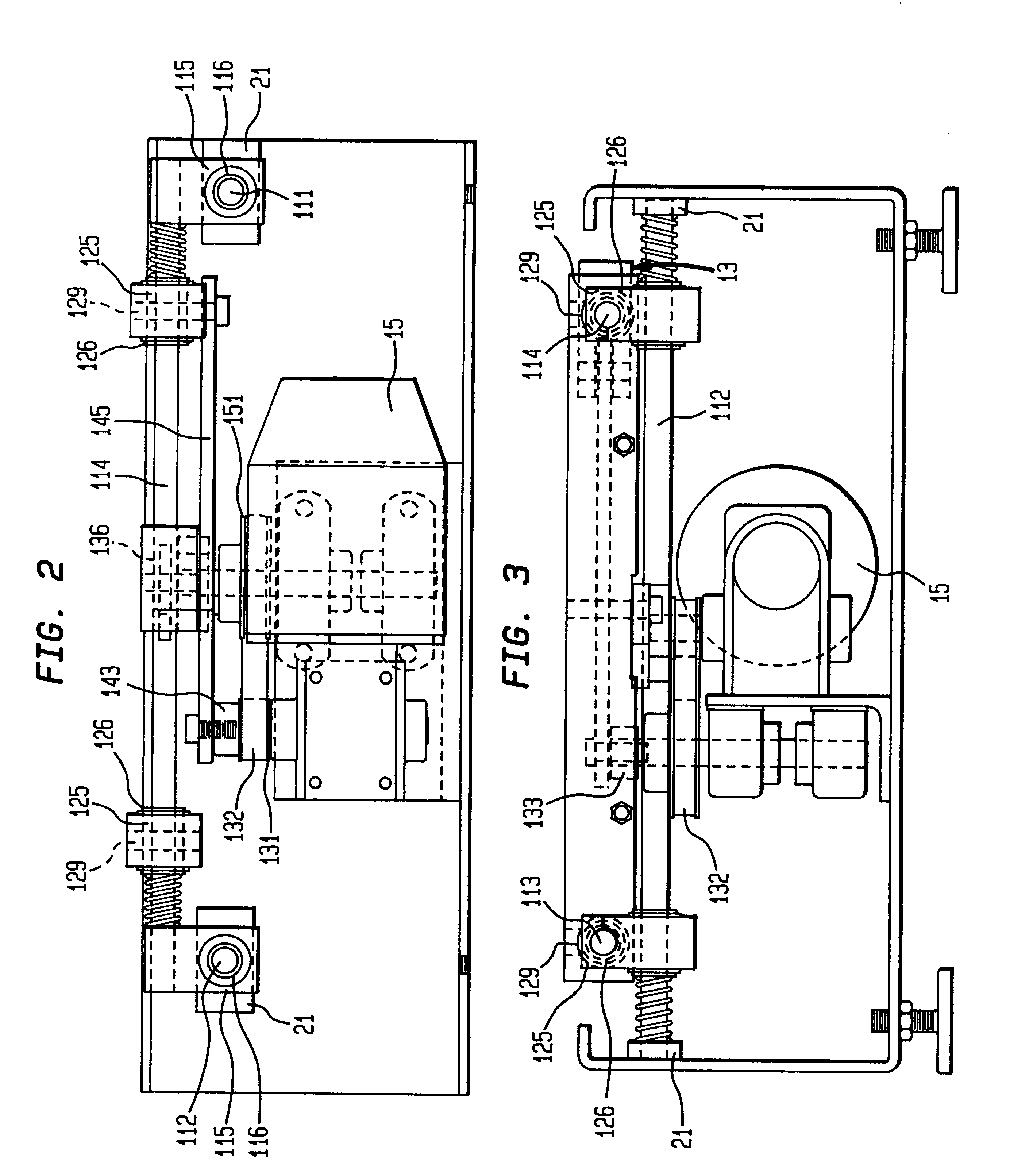
In short, this invention is a rotatory shaker movement which independently controls the horizontal and vertical motions of a shaker platform. The combination of these independent movements can produce an arbitrary path of motion in the shaking action, including, if desired the traditional circular and linear reciprocating ones. Thus, the shaking action can be optimized for each type of mixing application. The liquid being shaken can be more thoroughly mixed, with less power input, and at a lower angular frequency than is practical with prior art shakers. Also, this invention allows higher rates of mass transfer at equivalent levels of energy input.

Problems solved by technology

Consequently, the motion of one element of liquid relative to another is poor.
Thus, mixing is accomplished entirely by viscous action, and at high fluid viscosities, the quality of mixing may become quite poor.
These tactics are often helpful, but they do not solve the underlying problem, which is the mixing limitations inherent in the shaker's basic pattern of motion.
However, these reciprocating designs suffer from excessive splashing even at relatively low shaker rates.
This splashing is often unacceptable because it results in excessive spillage (from open containers) or contamination (from touching the stopper in closed containers).
Furthermore, there exists a fundamental limitation in these prior art shaker designs that cannot always be overcome either by more vigorous rotatory shaking or tolerating the inherent spillage / contamination in reciprocating shaking.
In some instances, it is not possible to exchange gases rapidly enough, and the flask becomes "mass transfer limited".
Such operations are not reproducible.
Thus, they may yield unreliable results.
All current designs frequently run at the limits of their capabilities.

Method used


Image

  • Reversing rotatory shaker movement
  • Reversing rotatory shaker movement
  • Reversing rotatory shaker movement

Examples


experiment 1

Inoculum--5 ml of Washed Slant in Each Flask

In this experiment, both shakers were running at the same speed.

experiment 2

Inoculum--5% From Actively Growing Flask

In this experiment the prior art shaker was running at a higher rate than the shaker incorporating the instant invention.

experiment 3

Inoculum--10% From Actively Growing Flask

In this experiment, the rate of shaking in the prior art shaker was higher than the previous experiment while the shaker setup incorporating the instant invention was kept at the same shaking rate. The inoculum was also increased to 10%.

Although this invention has been described with a certain degree of particularity, it is to be understood that the present disclosure has been made only by way of illustration and that numerous changes in the details of construction and arrangement of parts may be resorted to without departing from the spirit and scope of this invention. For example, separate synchronized motors could also be used to drive the cranks, allowing for arbitrary frequency ratios without the need to physically change pulleys. Also, gears could be used instead of belts and pulleys to control the cranks. Cams and slot plates or cams and springs would also be suitable. In fact, use of cams and springs would permit arbitrary amplitude o...


PUM


Abstract

A shaker movement permits an arbitrary path of motion in a shaker's shaking action. The shaker movement comprises independent control over the "X" and "Y" directions of the shaking actions by a pair of track assemblies, each track assembly comprising a pair of fixed rods and a pair of sliding rods that are interconnected with each other in a rectangular, grid-like pattern. Motion in both directions can be driven by a single motor utilizing independent pulley-and-belt systems or by two synchronized motors which are connected to a sliding rod of each track assembly. By altering the relative amplitude, phase angle, and frequency between the "X" and "Y" directions, the shaking action can follow a desired path. The shaker path can be varied from the traditional circular orbital motion or linear motion, to a new group of shaking patterns in which the direction of the shaking movement can reverse. The new patterns of shaker movement cause the liquid being shaken to be more thoroughly mixed, with less power input, and at a lower angular frequency than is practical with traditional paths of motion. This results in higher rates of gas transfer to and from the liquid, resulting in greater growth of a bacterial culture, and for higher rates of mass transfer at equivalent levels of energy input.

Description

1. Field of the InventionThis invention relates to shaking devices for flasks and other containers holding liquid mixtures which are used in biological and other applications, and more particularly to reversing rotatory shakers.2. Description of the Prior ArtShakers have been employed for many years for a variety of applications in the chemical, biological, metallurgical, and other industries. Shakers impart a mixing motion to a liquid which is contained in one or more flasks. The flasks, usually made of glass or a polymer, are attached to a platform on the top of the shaker. Because the flasks are so located, they are often referred to as "shake flasks".Shakers are sometimes enclosed in an environmental chamber held at a controlled temperature. The chamber often becomes an integral part of the shaker, but the device may also be placed in a controlled temperature room. Special lights may be incorporated in the shaker chamber when photosynthesis is desired.One common application of s...

Claims


Application Information

Patent Timeline
IPC IPC(8): B01F11/00
CPCB01F11/0025B01F31/25B01F31/22
Inventor BULL, DANIEL
Owner BULL DANIEL
Learn More