Minimally invasive surgical apparatus

a surgical device and minimally invasive technology, applied in the field of surgical retractor devices, can solve the problems of not having complete access to the surgical field, devices that are not particularly effective in limiting the motion of the heart, and the operation on a beating heart is technically difficult, so as to facilitate the access to the opening mechanism, stabilize the retractor, and reduce the trauma to the patient

Inactive Publication Date: 2001-11-27
SMITH & NEPHEW INC +1
View PDF47 Cites 250 Cited by
  • Summary
  • Abstract
  • Description
  • Claims
  • Application Information

AI Technical Summary

Benefits of technology

The screw gear extends between the toothed proximal ends 4a and 6a of the frame members 4 and 6 at an angle of approximately thirty degrees, forming an angled worm gear 10 assembly. The screw gear 10 turns on a guide pin 10a that is connected to the connector plate 8. A cover plate 14 sits on top of the connector plate and proximal ends 6a and 4a of the frame members 4 and 6. The cover plate 14 has a conforming angled screw slot 14a to further guide the screw.
Turning the screw 10 drives the helical worm face against the teeth of both proximal ends 4a and 4b of the frame members 4 and 6, causing the frame members 4 and 6 to pivot in opposite senses substantially in the x-y plane so the two members 4 and 6 draw toward each other, or push apart from each other, depending on the direction of rotation. This angled worm gear 10 has advantages. The angled worm gear 10 allows the gear to be self locking, i.e. the retractor can be opened to a fixed separation and it will maintain that separation. Furthermore, the angle of the worm gear 10 facilitates access to the opening mechanism by the retractor operator while maintaining access to the incision.
The frame members 4 and 6 include retractor blades 19 and 21, which extend down, transverse to the x-y plane of the frame members 4 and 6. These blades are placed in an incision when the retractor is in a closed position, i.e. when the frame members are in relative spatial proximity to each other. Upon placement of the retractor blades in an incision, the screw can be screwed down into the worm gear causing the frame members to open outwardly and the retractor blades to exert outward pressure on the walls of the incision 15 and 17, and consequently spread and keep open the incision. The frame members, the retractor blade members and the connector plate are made of a strong metal, e.g. stainless steel or titanium.
The blades 19 and 21 are modular, i.e. the blades 19 and 21 are removably and replaceably attachable to the retractor. The blades 19 and 21 can pivot about a substantially vertical axis, as shown so that they conform to the orientation of the incision, or pivot about a substantially horizontal axis. In the embodiment shown in FIGS. 2A and 2C, the blades are angled back, i.e. they tilt outwardly as they extend down, so the angle between the blade and the frame member in the y-z plane is less than 90 degrees. As the blades spread apart an incision, the pressure provided between the blades and at least a wall portion of the incision has a downward component of force, driving the retractor down against the patient's body, stabilizing the retractor. Furthermore, a blade can include a compliant blade element such as an attachable conforming elastomeric pad that attaches to the blade. Such a compliant blade element evenly distributes pressure over at least a wall portion of the incision, reducing trauma to the patient.
With reference to FIGS. 2B and 4, the retractor of this embodiment also includes fiber optic light guide 63 optically coupled to a light source. In one embodiment, the light guide is bifurcated with each individual light guide running along light guide mounts. Individual light guide 64a travels along light guide mount 65a to a distal end of the frame member 66f, where it is optically coupled to a light wand 66, which is preferably disposable. The light wand provides light to the surgical field while its disposability facilitates sterilization of the retractor.

Problems solved by technology

However, surgery on a beating heart is technically difficult, especially when performed through a small incision between ribs.
However, these devices are not particularly effective in limiting the motion of the heart and they require that an assistant place at least one hand near the surgical site.
However, the implements of these assemblies do not have complete access to the surgical field.
In other words, the mechanisms which attach the implements to the retractor assemblies allow only limited freedom of movement.
Thus, if a surgeon uses such a configuration and adds further specialized surgical implements, the limited freedom of movement might complicate the surgery.
For example, when a surgeon creates an incision for heart surgery and places a retractor, the heart is still covered with the pericardial membrane, an opaque tissue, and the surgeon can not clearly determine the location of the artery of interest at this point in the surgery.
To disassemble and re-configure a retractor and associated surgical implements takes time, and puts the patient at risk of complications.

Method used


Image

  • Minimally invasive surgical apparatus
  • Minimally invasive surgical apparatus
  • Minimally invasive surgical apparatus

Examples


example 2

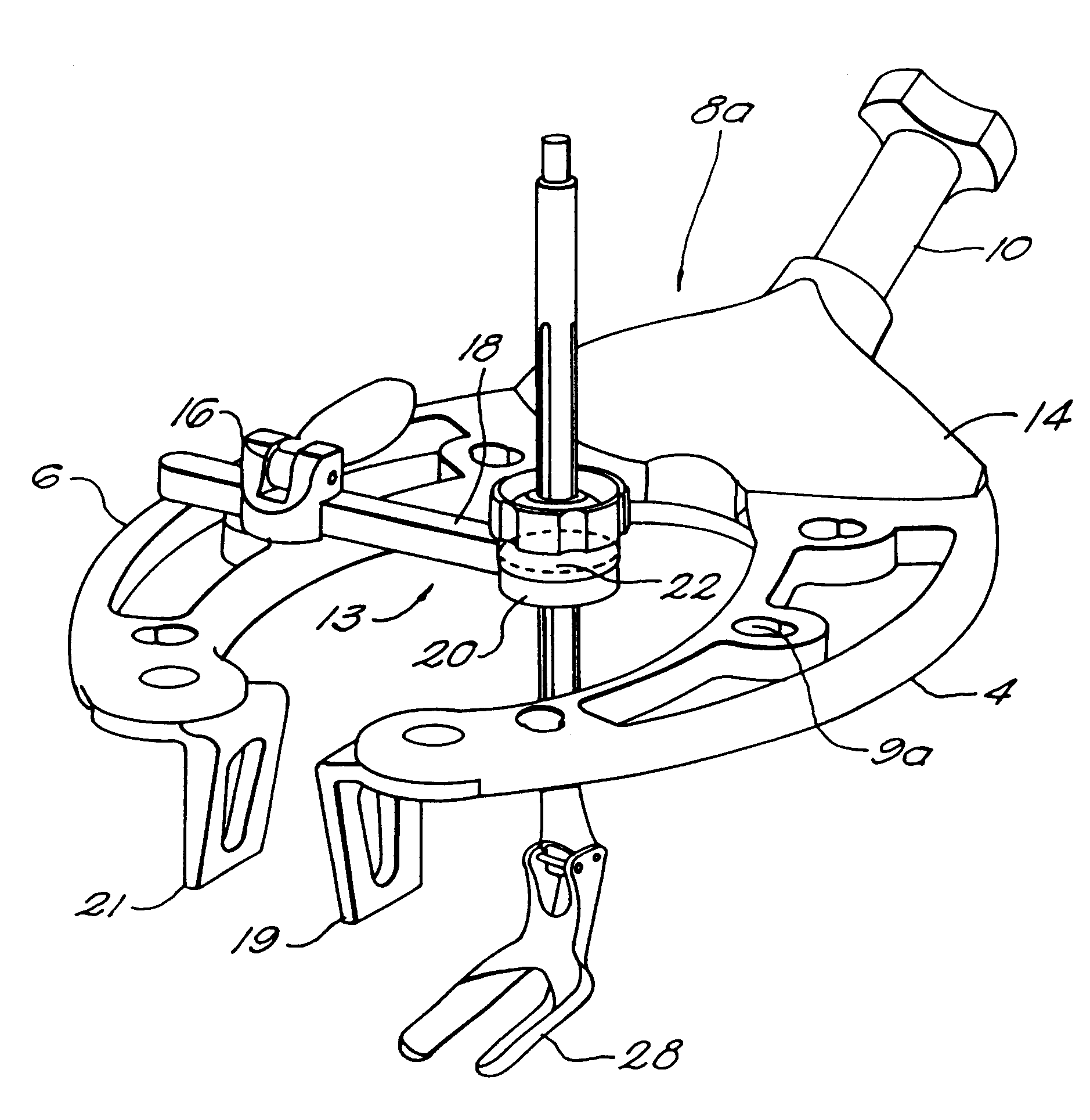
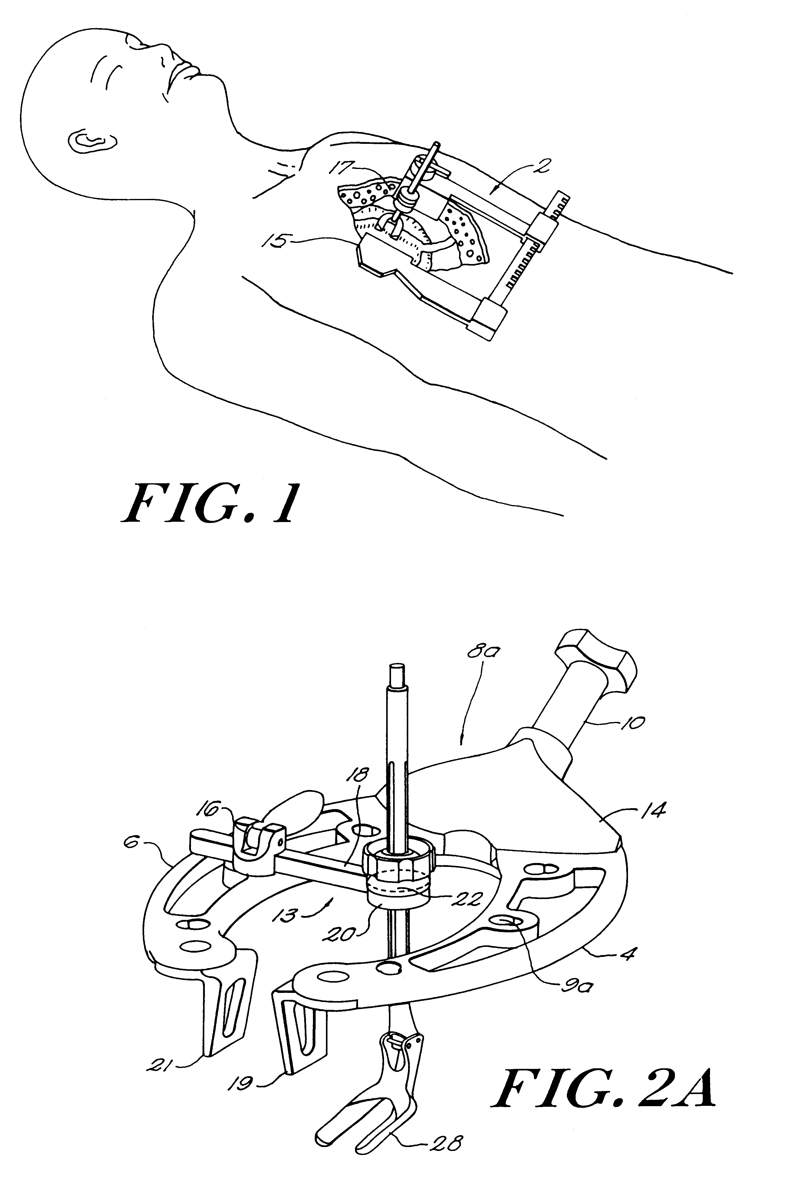
Referring to FIGS. 11A-13, another embodiment of a retractor and surgical tool attachment system according to the invention comprises a retractor 102 for spreading and keeping back the walls of an incision in the patient. The retractor includes first and second retractor frame members 104 and 106. The second frame member 106 similar in configuration to the first frame member, has a toothed proximal end 157. The toothed proximal end of frame member 106 sits on the proximal end 159 of the first retractor frame member. An opening mechanism 150, sits on the proximal ends of the frame members and comprises a cover plate 155 and a series of gears 151. The gears fit into slot 143 in the second retractor frame member and a further slot 141 in the first retractor frame member. The retractor frame members pivot around a shaft 161 extending down from the cover plate. The cylindrical shaft inserts in slots 163 and 165 of second retractor frame and first retractor frame, respectively. The openin...

example 3

With reference to FIGS. 14A-15B, an embodiment of the retractor and surgical tool attachment system according to the invention comprises a retractor 202. The retractor includes a substantially L-shaped stationary section 208 which has a stationary frame member 204 and a moveable frame member 206. The moveable frame member, similar in configuration to the stationary frame member, has a toothed cross bar or rack 210 attached to it. The stationary frame member has a housing 212, which slides on the rack. The substantially L-shaped stationary section also includes an opening mechanism crank lever 252. Rotating the crank lever rotates a gear in the toothed cross bar of the moveable frame member alternatively moving the moveable frame member in or out.

Both frame members include universal mounting grooves 270. These mounting grooves allow an extension device 213 to be slideably positioned along the frame member within the groove.

The extension device includes a push-button clamp assembly 21...

example 4

Referring to FIGS. 16A-17B, another embodiment of a retractor and surgical tool attachment system according to the invention comprises a retractor 302. The retractor incorporates the general shape of Example 2 with the universal mounting groove of Example 3. The opening mechanism comprises a foldaway crank lever 352 a gear 357 attached to the crank lever, and, a cover plate 355. The retractor comprises a first retractor frame member 304 and a second retractor frame member 306. The proximal end of the second retractor frame member sits on top of the proximal end of the second retractor frame member. The opening mechanism sits on the proximal ends of the frame members 304 and 306. The proximal end of the second retractor frame member 306 has a slot 393 with ratchet teeth 392. The gear 357 of the opening mechanism fits in the slot 393 of the second frame member 306. By turning the crank lever 352 which is attached to the opening mechanism gear 357, the gear 357 rotates against the ratc...


PUM


Abstract

The present invention encompasses tools and a tool-holding retractor assembly. The retractor assembly spreads an incision and holds the incision open. At least one extension device, having a tool holder on one end, attaches to the assembly. The holder includes a selectively locking multi-axis adjustable mounting element adapted to grip a tool shaft. The mounting element acts as a universal mounting providing rotational and sliding movement of the tool shaft. The extension device adjusts to position the tool holder peripherally of the surgical field. Once the retractor is placed, the extension device provides full access to regions below the incision. The extension device allows the surgeon to chose the insertion point and insertion angle of the tool shaft.

Description

Minimally invasive or video assisted surgical procedures are being developed to reduce trauma, surgically induced complications, and costs associated with a lengthened hospital stay. One common, and costly operative procedure in the US is coronary artery bypass grafting (CABG), therefore, considerable attention has been given to establishing procedures for performing CABG surgery as a minimally invasive operation. Two basic approaches are currently being investigated by cardiac surgeons:CABG (and other heart) operations on an arrested heart with percutaneous cardiopulmonary bypass (CPB); andCABG procedures on a beating heart without cardiopulmonary bypass.There are certain advantages to the second approach in that CPB is known to be associated with some complications that can occur in open heart surgery. However, surgery on a beating heart is technically difficult, especially when performed through a small incision between ribs. Thus, there is a need to facilitate CABG surgery on a ...

Claims


Application Information

Patent Timeline
Patent Type & Authority Patents(United States)
IPC IPC(8): A61B17/02A61B19/00
CPCA61B17/0206A61B2017/0243A61B2019/5206A61B2090/306
Inventor SIKORA, GEORGEBEANE, RICHARDSTAHL, RUSSELL F.SOLLER, BABS R.EK, STEVEN W.MCCARTHY, GARYDAVIS, BILLVERDURA, JAVIER
Owner SMITH & NEPHEW INC
Why Eureka
Try Eureka