
PTFE window seal with EMI shielding

a window seal and shielding technology, applied in the field of process window seals, to achieve the effect of reducing the shear stress of the ptfe, increasing the pressure rating, and high corrosive materials

Inactive Publication Date: 2001-12-04
ROSEMOUNT INC
View PDF17 Cites 56 Cited by
  • Summary
  • Abstract
  • Description
  • Claims
  • Application Information

AI Technical Summary

Benefits of technology

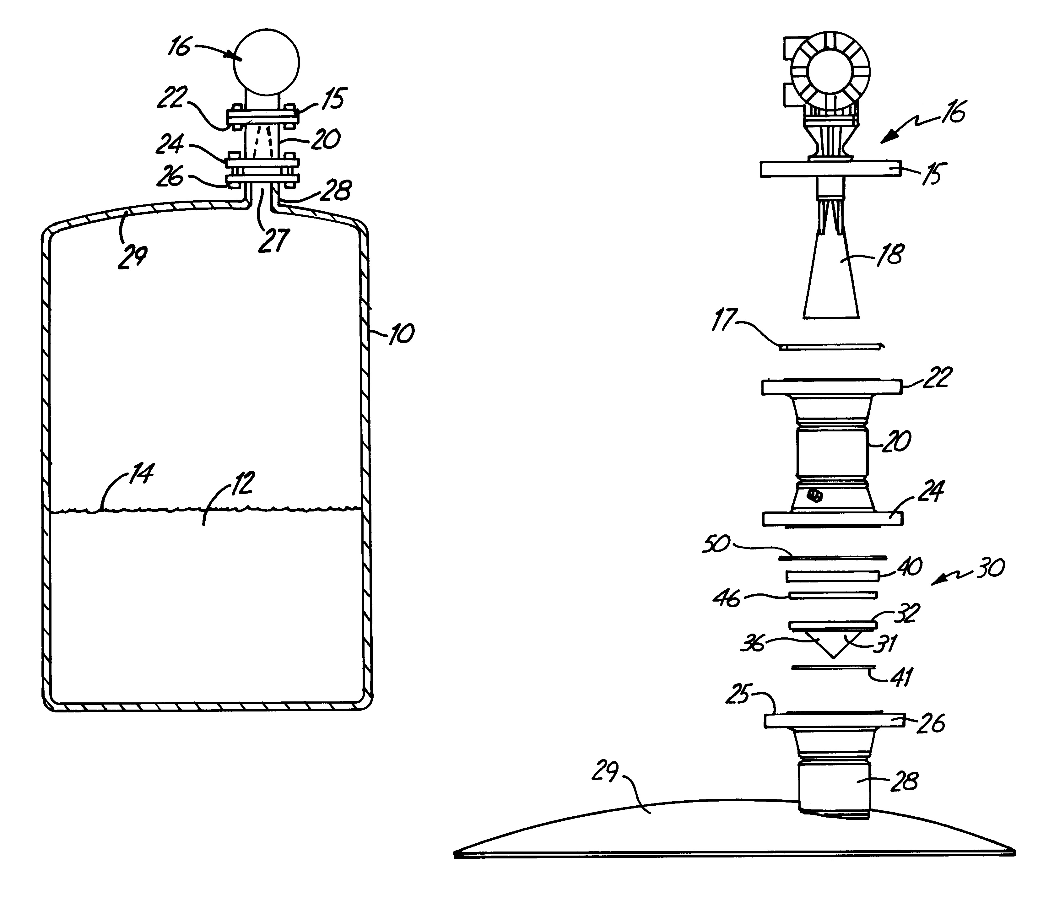
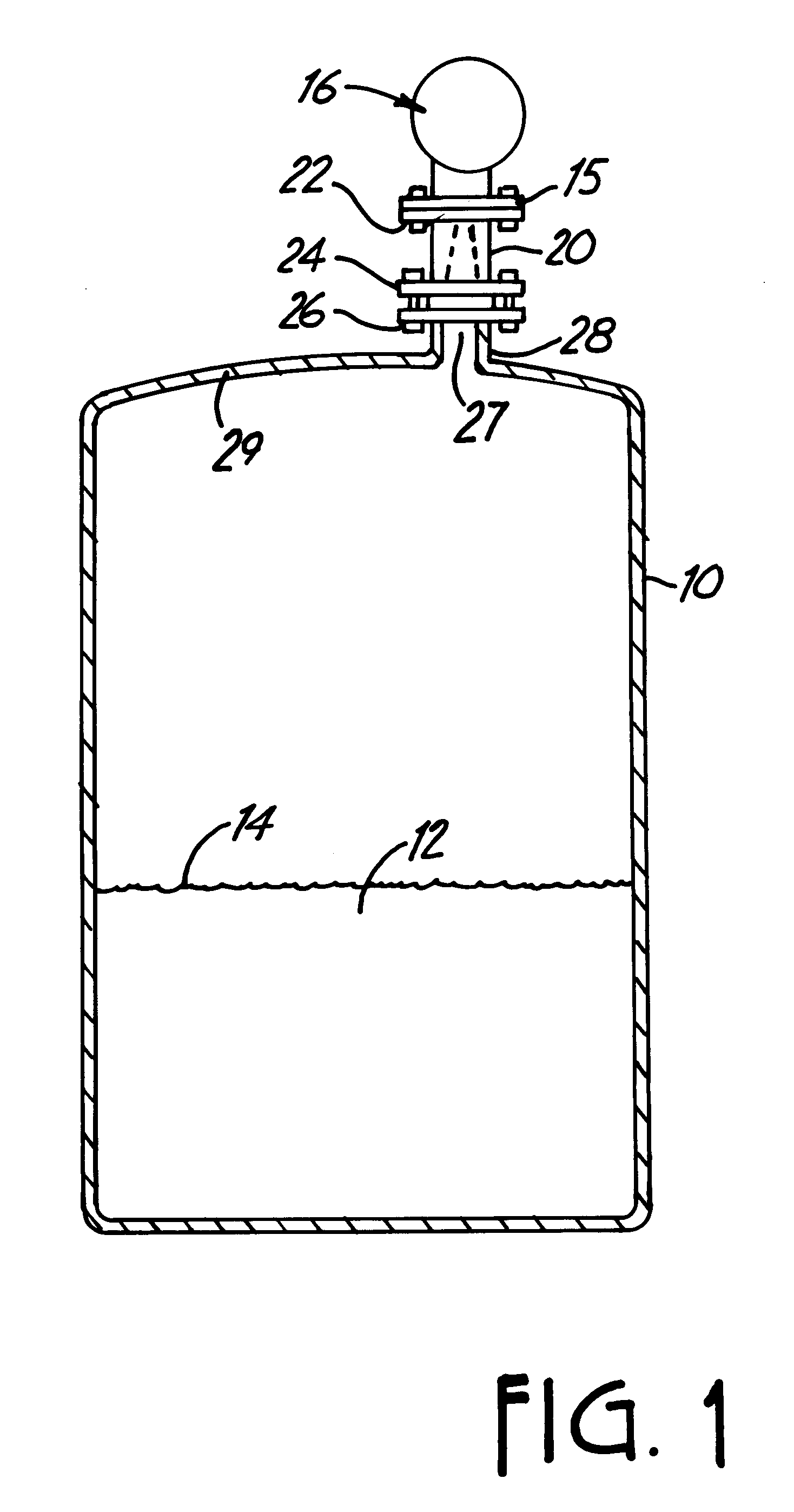
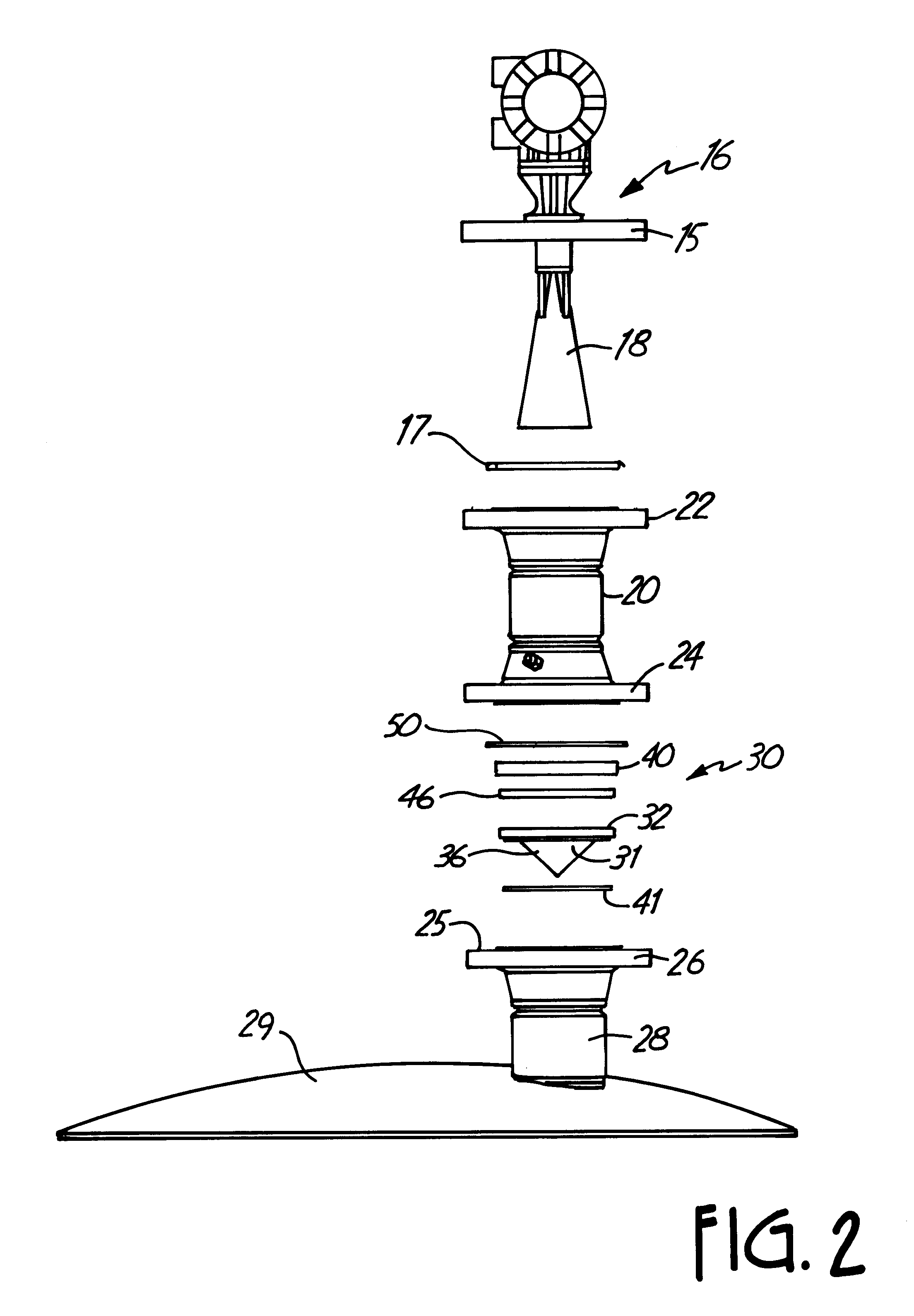
The container as shown is a process fluid tank on which a microwave radar level gauge or transmitter is mounted. As shown, a support flange of the window seal is clamped between the bounding surface on the tank flange on the customer's tank, and a stand off pipe that surrounds a horn antenna on the microwave level gauge or transmitter. The clamping of the microwave window seal member between flanges will retain it securely, and create a seal, but under high tank pressures, and high temperature and humidity, and with highly corrosive materials, the preferred PTFE material for the window seal member will tend to cold flow or to creep. Creep can occur even under lower temperatures when the pressures are high. The containment ring surrounding the window seal member controls the amount of creep or cold flow radially outwardly, thereby reducing the shear stress in the PTFE and increasing the pressure rating for a given temperature in a comparable size seal.
The containment ring helps to maintain the shape of the PTFE window seal member over time. The containment ring preferably has an inwardly extending lip that overlies a portion of the seal flange. Clamping forces are applied to the containment ring, and the lip provides a cross sectional area engaging the seal flange on which the applied clamping loads act that is less than the stand off pipe flange. Also, the load from pressure in the process fluid tank is applied over this smaller cross sectional area defined by the lip of the containment ring. Shear stress is reduced and the pressure rating is increased.
A metal, spiral gasket is used above the lip of the containment ring and is clamped in place with the stand off ring to further increase the integrity of the seal.

Problems solved by technology

The clamping of the microwave window seal member between flanges will retain it securely, and create a seal, but under high tank pressures, and high temperature and humidity, and with highly corrosive materials, the preferred PTFE material for the window seal member will tend to cold flow or to creep.

Method used


Image

  • PTFE window seal with EMI shielding
  • PTFE window seal with EMI shielding
  • PTFE window seal with EMI shielding

Examples


Embodiment Construction

A process tank or container 10 as shown has a process liquid 12 therein with a surface 14, the height of which surface 10 is to be determined relative to the bottom of the tank. A radar gauge or transmitter 16 that transmits microwave energy through a horn antenna 18, is positioned at the top of the tank 10. The radar gauge or transmitter 16 is mounted on a cylindrical stand-off pipe or spool piece 20 that has a top flange 22 on which a flange 15 of the radar gauge or transmitter 16 is mounted. A spiral wound metal gasket 17 may be used between flanges 15 and 22 (FIG. 2). The stand off pipe 20 is cylindrical and surrounds the horn antenna 18 in the form shown.

The stand off pipe 20 has a bottom flange 24 that is of standard size bolt pattern and shape (ANSI or DIN standard) to mate with a bounding support surface 25 of a standard size mounting flange 26 on the top of a nozzle or neck 28 on the tank 10. All flanges have industry standard bolt circles. The nozzle or neck 28 is fixed to...


PUM


Abstract

A process seal made of a material such as polytetrafluoroethylene is used as a microwave window in a radar tank level gauge. The periphery of the process seal is surrounded by a metal containment ring that is fitted to the periphery to limit the amount of expansion outwardly of the process seal material as well as provide for localized loading at the periphery for clamping pressures on the seal. Electromagnetic radiation shielding is provided not only by the containment ring, but also by an EMI shielding O-ring mounted in a groove on a sealing end of the containment ring. A process environmental O-ring is carried by the process seal in an outer shoulder groove that is enclosed by the containment ring.

Description

BACKGROUND OF THE INVENTIONThe present invention relates to a process window seal that will transmit microwave energy and includes a surrounding ring with seals to reduce or prevent microwave energy leakage. The ring contains the window seal to avoid creep or cold flow across a wide range of temperatures to avoid failures under operating pressures.In the past, there have been considerable developments in the use of microwave (radar) gauges for determining tank levels. These gauges depend upon transmitting microwave energy toward a surface of material inside a tank or container, and then receiving an echo or return signal to determine the level of the material sending the echo. The correct type of device depends in part on the overall distance that needs to be measured, that is the height of the material in the tank between its lowest level and its highest level. Also, the surface conditions of the materials are of importance in measuring tank level, as are the dielectric constant or...

Claims


Application Information

Patent Timeline
IPC IPC(8): G01F23/284G01F23/292
CPCG01F23/284G01F23/292Y10S277/92
Inventor SMITH, DENNIS J.OLSON, RANDALL C.KRUSE, STEVEN D.
Owner ROSEMOUNT INC
Features
  • Generate Ideas
  • Intellectual Property
  • Life Sciences
  • Materials
  • Tech Scout
  • Unparalleled Data Quality
  • Higher Quality Content
  • 60% Fewer Hallucinations
Learn More