Gauge for measuring large diameter

a gauge and large diameter technology, applied in the direction of mechanical diameter measurement, measurement devices, instruments, etc., can solve the problems of large deformation, high cost, poor repeatability, etc., and achieve the effect of small volume, high accuracy and simple structur

Inactive Publication Date: 2001-12-18
SOUTHEAST UNIV
View PDF16 Cites 19 Cited by
  • Summary
  • Abstract
  • Description
  • Claims
  • Application Information

AI Technical Summary

Benefits of technology

The purpose of this invention is to provide a large diameter gauge that has the features of simple structure, small volume, high accuracy and good versatility. After marking down the parameters of the measuring units tightly placed around the workpiece and getting the closed size by measurement, an equation with the diameter to be measured as the variable can be obtained according to the geometric relations. Then, the diameter of the workpiece can be solved from this equation.
2. Simple structure, compact volume and easy to be operated. Even one person can accomplish the whole measurement.
5. High precision. Because the central distance of the gauges and the diameters of the roller and the ball can be calibrated accurately, and the measurement is performed on the whole circumference of the workpiece, the method has very high precision.

Problems solved by technology

The characteristic of measuring large diameters is that the measuring apparatus is usually with large dimension and heavy weight, which leads to many problems such as much difficulty of operation in situ, complexity of calibration, large deformation and high cost.
(1) Since the slippage of the roller on the surface of the workpiece is inevitable, it usually suffer the problem of bad repeatability and limited accuracy, which is the vital disadvantage of this method.
(2) The measuring apparatus is complex and expensive.
(3) Because the workpiece must revolve while measuring, it can only be employed on machine.

Method used


Image

  • Gauge for measuring large diameter
  • Gauge for measuring large diameter
  • Gauge for measuring large diameter

Examples


first embodiment

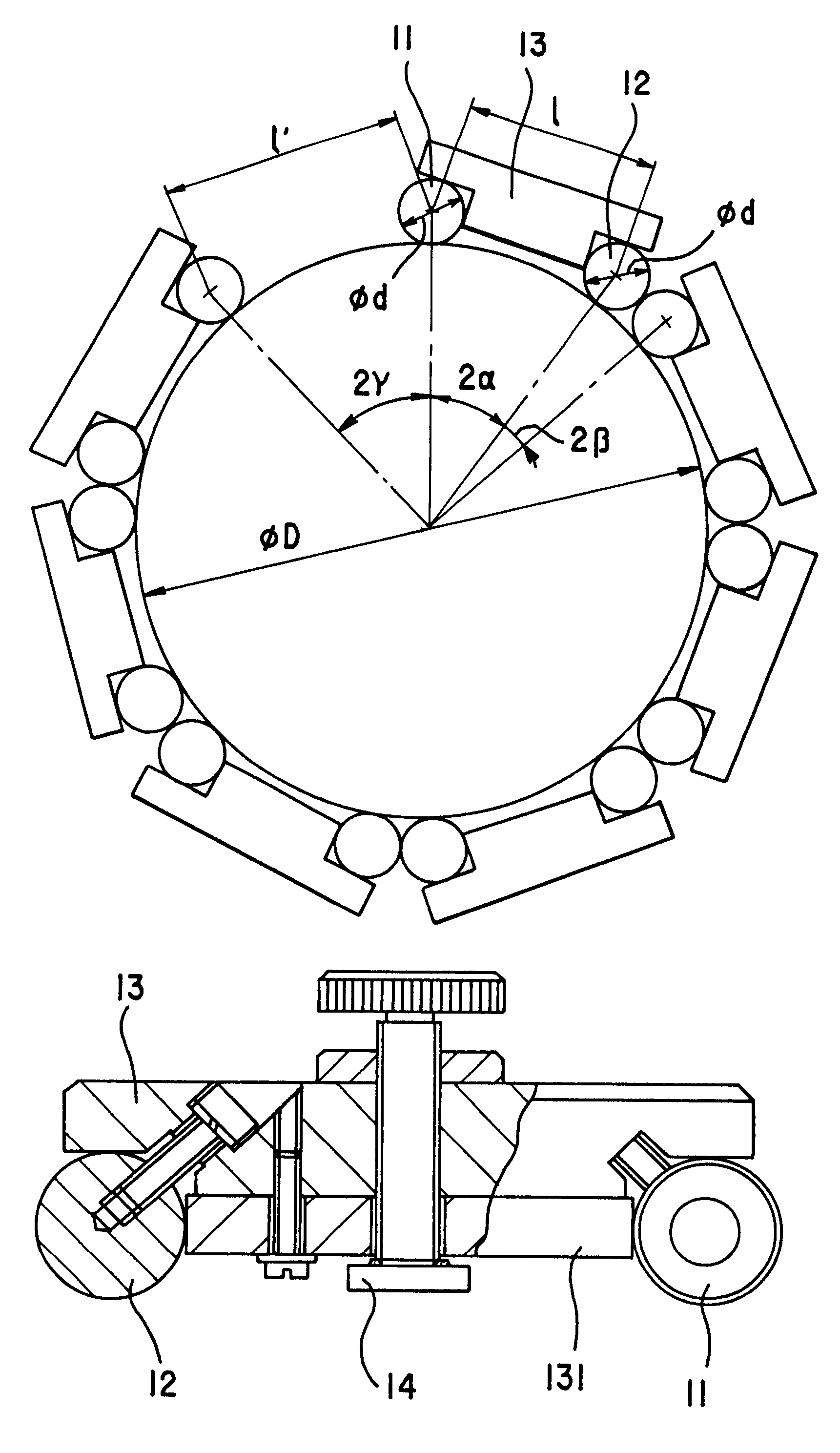
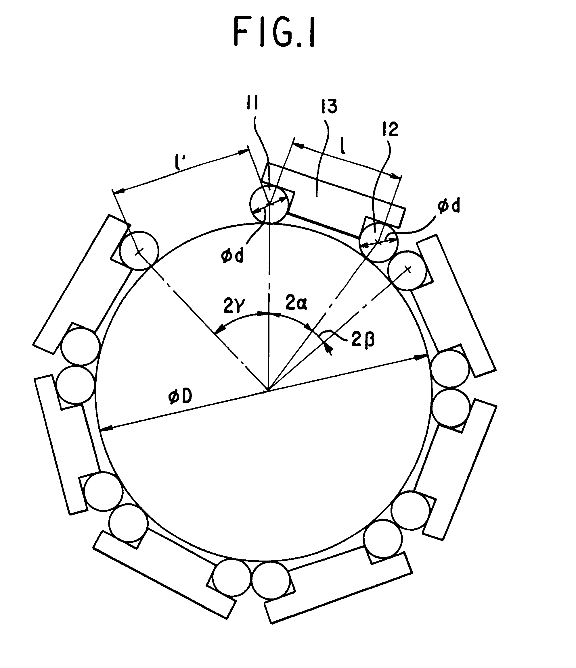
As shown in FIG. 1, positioning elements 11 is a roller, but 12 can be a ball or a roller. When the two positioning elements are rollers, their axes should be parallel each other. The two positioning elements are fixed at the two ends of the body 13. A measuring block 131 is also installed on the body 13, its two ends contact with the two positioning elements (FIG. 2). The accuracy and accordance of each gauge's central distance can be guaranteed by current manufacturing technology of standard blocks. There is an adjustable screw at the center of the body 13. A fastener 14 of permanent magnet is arranged at the end of the screw. The above-mentioned elements form a measuring gauge of this invention. The measuring gauges are attached and fixed firmly on the out- or in-circumference of the steel- or iron-made workpiece by fastener 14. The magnet force between the gauge and workpiece can be adjusted by turning the screw. In order to improve the contacting condition between the end surfa...

second embodiment

When the diameter of the workpiece is very large, the size of the gauge is large also. The fastener 14 is a magnetic-force-conversion device with a main permanent magnet 142 and a handle (FIGS. 6,7). The fastener is located on the middle of the gauge. While turning the handle, the magnetic path can be switched-off and switched-on. Thus, the magnet force can be created or eliminated. The principle of it is the same as that of the magnetic gauge stands applied in the filed of precision measurement. If necessary, the auxiliary magnets 141 can be set at the both side of the magnetic-force-conversion device. They are fixed on the screws. Their magnetic force is smaller than that of the main magnet. By turning the screws, the distance and then the magnetic force between the two auxiliary magnet s and the workpiece can be adjusted. The aim of employing the auxiliary magnets is to simplify the operation. That is, firstly have the main magnet do not work, then place the gauge to the workpiec...

third embodiment

As shown in FIG. 8 and FIG. 9, the body of the gauge is mainly composed of the pole or pipe 131, left brace block 132 and right brace block 133. The reason of employing the pole or pipe 131 as the main part of the body is to increase the length of the gauge and then the measuring efficiency. Because the gauge is long, two permanent magnets 141 and 142 are arranged at both sides of the gauge to ensure the enough magnetic force. Wherein 141 is located within the right brace block 133 (not shown) as the same way like 142 within the left one. The positioning element 12 is a roller in FIG. 8 and FIG. 9. It can be a ball also.


PUM


Abstract

A large diameter gauge consists of a series of measuring units. Each measuring unit comprises two positioning elements(11,12), a fastener(14) and a body(13). These series of measuring units are placed and fixed sequentially and head to end or end to head around the circumference of the cylinder or hole to be measured during measuring until the remained space is not large enough to be put into another one measuring unit. Measuring the distance between the first measuring unit and the last measuring unit, the diameter to be measured can be obtained through the geometric relations between the gauges and the cylinder or hole to be measured.

Description

TECHNICAL DOMAINThis invention relates to a measuring apparatus and method that bears the characteristics of employing mechanical method to measure large-diameter-workpiece; especially using with compact measuring apparatus, in the field of measuring technology.BACKGROUND OF THE TECHNOLOGYThe characteristic of measuring large diameters is that the measuring apparatus is usually with large dimension and heavy weight, which leads to many problems such as much difficulty of operation in situ, complexity of calibration, large deformation and high cost. The roller way (Page 21-22, Volume 1, Foreign Metrology, 1991) provided a method to measure large diameters with compact measuring apparatus. It is necessary to include many parts in such method, such as the roller, badge, sensor of revolution, sensor of compaction, disk of glass grating, pulse counter, microprocessor, keyboard, digital-displaying device and so on. The diameter of the workpiece is obtained by counting the revolution of th...

Claims


Application Information

Patent Timeline
Patent Type & Authority Patents(United States)
IPC IPC(8): G01B5/08
CPCG01B5/08
Inventor LI, BIN
Owner SOUTHEAST UNIV
Why Eureka
Try Eureka