Network switch failure restoration

a network switch and failure restoration technology, applied in the field of network switch failure restoration, can solve problems such as equipment failure and overload, failure to work normally, and serious consequences

Inactive Publication Date: 2001-12-18
THE TRUSTEES OF COLUMBIA UNIV IN THE CITY OF NEW YORK
View PDF6 Cites 71 Cited by
  • Summary
  • Abstract
  • Description
  • Claims
  • Application Information

AI Technical Summary

Benefits of technology

Further objects, features and advantages of the invention will become apparent from the following detailed description taken in conjunction with the accompanying figures showing illustrative embodiments of the invention, in which
FIG. 1A shows a planar network with seven network nodes;
FIG. 1B shows a network node with four connected bidirectional links;
FIG. 2B shows a flowchart of the steps that generate look-up tables for each network node;
FIG. 3A shows an example of protection cycles for a network node;
FIG. 3B shows an example of a cyclegroup;
FIG. 4 shows a node with two bi-directional merged cyclegroups;
FIG. 5 shows an example of a bidirectional merged cyclegroup resulting from the interconnection of two cyclegroups;
FIG. 6 shows a diagram of a node with a failed switch;
FIG. 7 shows a diagram of a 2.times.5 protection switch;
FIG. 8 shows a diagram of a 5.times.2 protection switch;
FIG. 9 shows an example of a detection system used in a node;
FIG. 10 shows a flowchart of the steps of the Orientable Cycle Double Cover (OCDC) technique;
FIG. 11 shows an example of the operation of the OCDC technique applied to a network;
FIG. 12A shows a second example of the operation of the OCDC technique for a network;
FIG. 12B shows a third example of the operation of the OCDC technique for a network;
FIG. 13 shows a non-planar network with 10 nodes and protection cycles and cyclegroups for nodes 2 and 4;
FIG. 14 shows a table indicating how the protection switches in network nodes 2 and 4 are interconnected in the example of FIG. 13;
FIG. 15 shows an example of a look-up table for node 2 in the example of FIG. 13; and
FIG. 16 shows an example of a node look up table for a four cyclegroup network.

Problems solved by technology

In currently deployed telecommunication networks, failures occur often, and sometimes with serious consequences.
An analysis of failures in the Public Switched Telephone Network (PSTN) has shown that human error, acts of nature, equipment failure and overloads are the major sources of failure.
Cable cuttings and equipment failures account approximately for half of the failures encountered in the network during that period.
The recent interest in restoration techniques for fiber optic networks is largely because fiber optic transmission systems are cable-based technologies that are subject to frequent damage.
Furthermore, due to the introduction of wavelength division multiplex (WDM) in commercial networks, each fiber can carry an extremely high volume of traffic and such failures can potentially affect a large number of customers, causing devastating effects to the network.
Taking into account that on the average each cable carries 96 fibers, there is a possibility that a cable cut will result in the loss of about 15 Tb / sec.
This in turn translates to the loss of 240 million voice circuits.
The most prevalent form of communication failures is the accidental disruption of buried telecommunication cables.
Fiber cuts may result, among other reasons, from construction work, lightning, rodent damage, fires, train derailments, vandalism, car crashes and human error.
One of the main reasons why telecommunication cables in the ground are so susceptible to failures is the fact that they are buried in the same public rights-of-way as are all other utility transport media (water, gas pipes, television cables, etc.).
As a result, when craftspeople for one utility company try to work on their transport medium, they usually affect the rest of the buried transmission media as well.
Because of that cut, an estimated 100,000 connections were almost immediately lost.
Manual restoration of some of the capacity on physically diverse routes took several hours, and the failure cost the telephone company millions of dollars.
Equipment failures, even though not as common as cable cuts, can also devastate the network.
In general, equipment failures affect many more customers than cable cuts, since all the connections passing through the failed network node are lost.
Equipment failures can result from natural phenomena (earthquakes, floods, fires), human error, as well as hardware degradation.
Examples of well-known equipment failures that had a devastating effect on the network include the 1988 fire that destroyed Illinois Bell's Hinsdale switching office, the 1987 fire that damaged N.Y. Telephone's Brunswick switching office and the 1987 AT&T switching computer failure in Dallas.
All three failures cost the telephone companies millions of dollars in business lost by the customers during the outage and more importantly diminished the customer's confidence in the companies' services.
Management of these networks is an important but difficult problem.
A network fault that goes unattended for a long period of time can cause both tangible and intangible losses for the company that provides the service, as well as for its clients.
A long outage may cause extensive revenue and asset losses, and seriously affect the services provided, and thus damage the credibility and reputation of an organization.
While prolonged outages can be particularly harmful, even brief ones can be troublesome.
Whereas previously in telephone networks an outage meant that a telephone caller had to hand up and try again later, an outage nowadays may have a devastating impact.
Thus, the current trend is for more and more networks that are virtually uninterruptible.

Method used


Image

  • Network switch failure restoration
  • Network switch failure restoration
  • Network switch failure restoration

Examples


Embodiment Construction

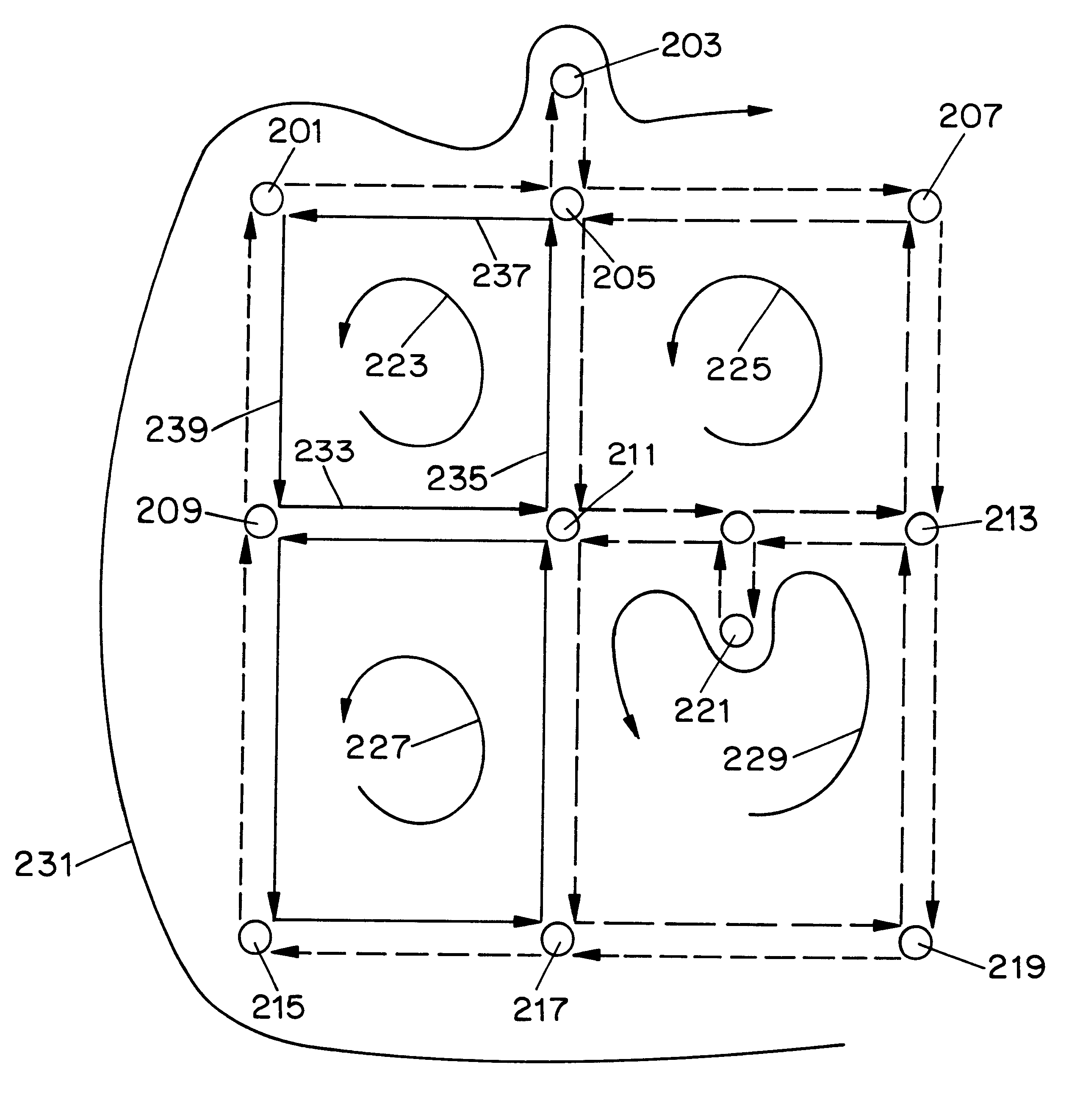
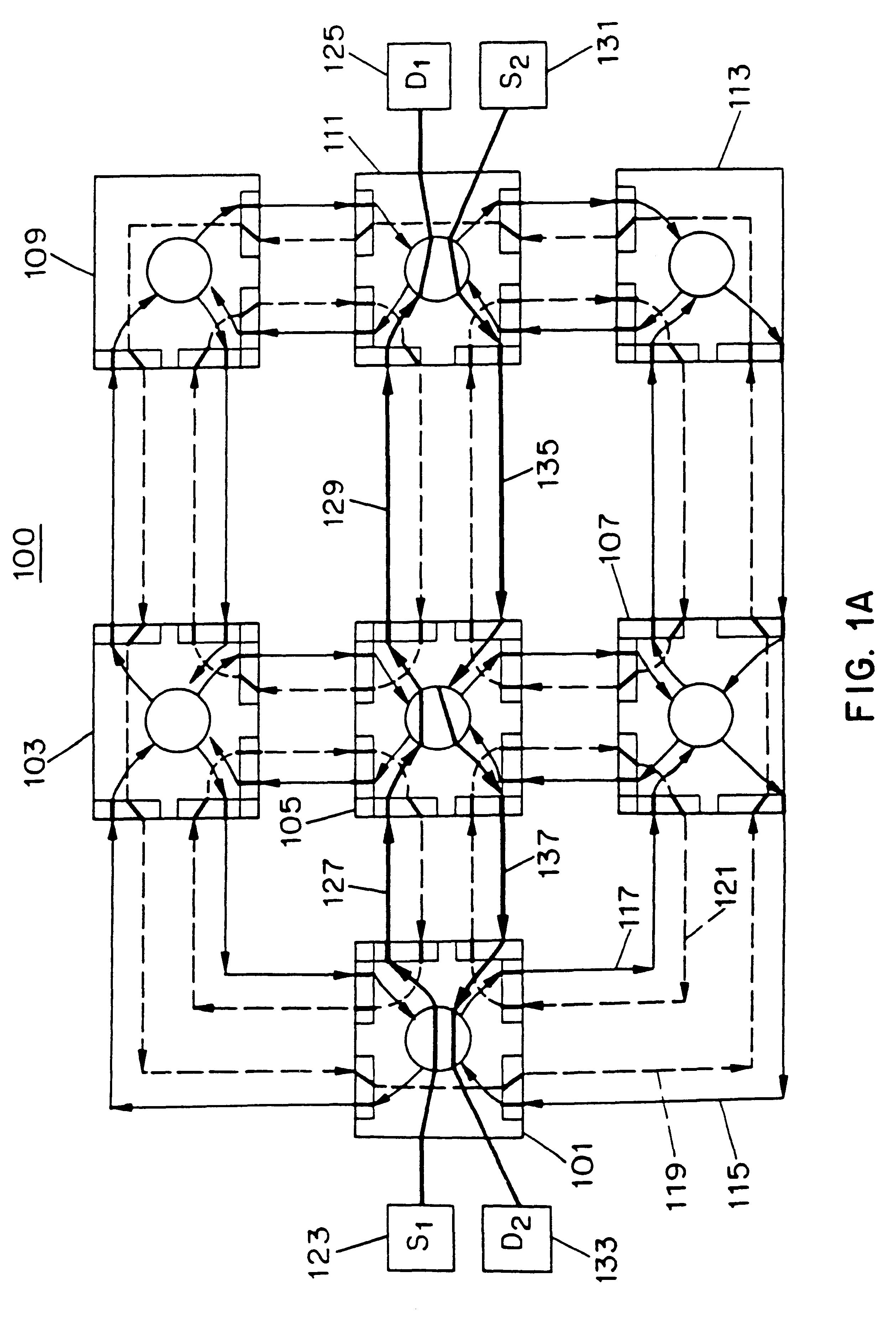
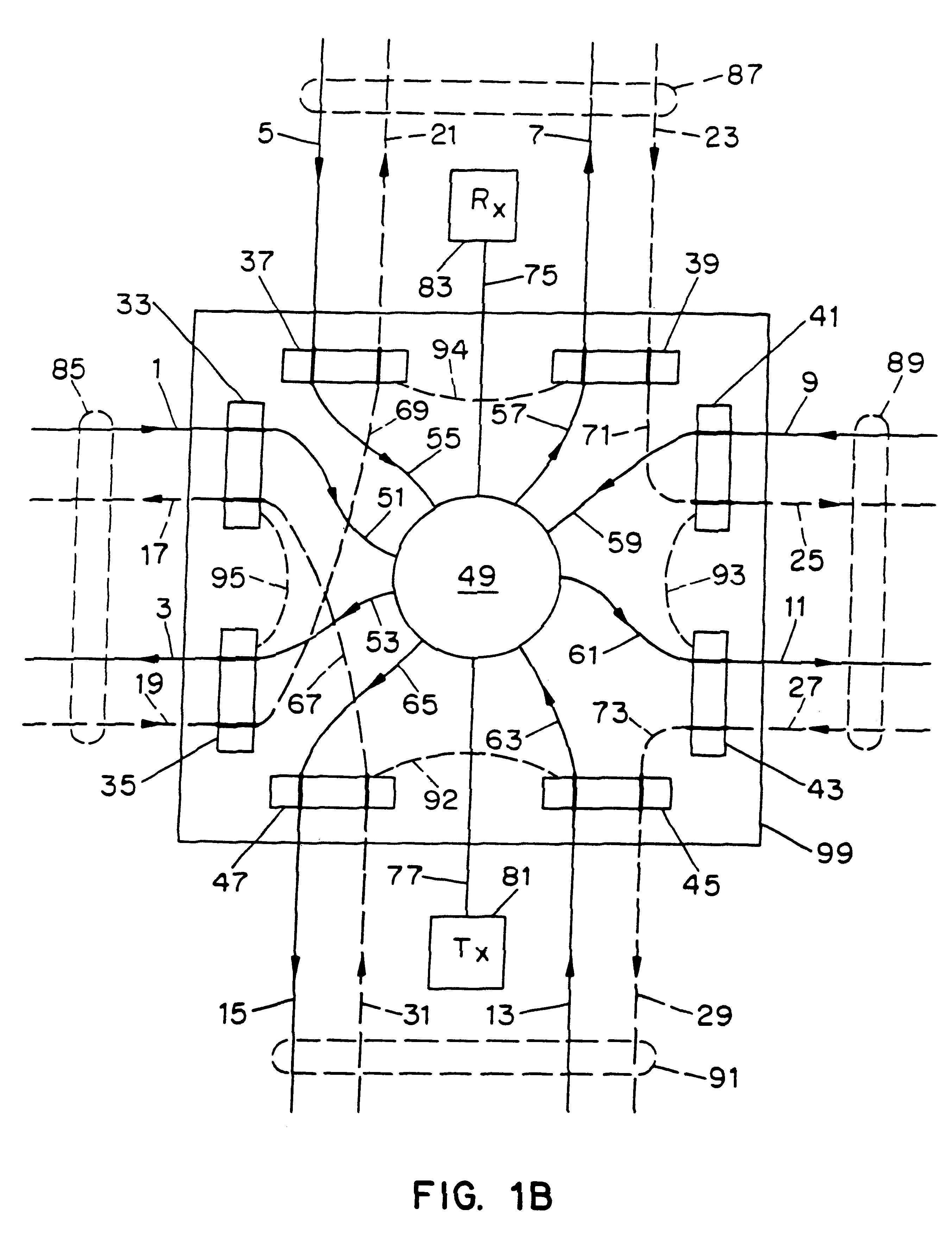
Automatic protection switching ("APS") for node failures requires rapid recovery from any failure of a network node. A network node is any station containing switching equipment (including protection switches) connected to one or more links and possibly end user equipment for the purpose of creating data paths between end users over successions of links and intermediate nodes. Links may be made up of one or more data conduits for transmitting data (including information in any form). In this preferred embodiment, optical fibers will be described as the conduits, so that a link will be composed of pairs of fibers carrying traffic in opposite directions. The central switches within nodes are preferably optical switches in this embodiment.

A network contains two or more nodes which are selectively connected together by links in a particular configuration. In this preferred embodiment, each link in a network contains a number of optical fibers, each of which carries data in a single dire...


PUM


Abstract

A system and method for automatically restoring a network which contains a node with a failed switch. Protection cycles are generated for the network to be restored and cyclegroups are generated from the protection cycles. Each node is provided with protection switches which internally interconnect the input / output ports to connecting links via interconnecting protection fibers. The selection of which internal protection fibers upon which to switch transmitted information onto allows the node to be configured to create merged cyclegroups. Thus if a failure in the central switch is detected, the transmitted information is diverted to a selected protection fiber corresponding to a merged cyclegroup so that the information can be automatically passed around the failed switch via the protection fibers. Each protection switch has associated mapping data which defines which protection fiber will be switched to based upon the input and output link for the transmission that is required to be sent through the node. The system and method applies to non-planar networks as well as planar networks.

Description

The present invention relates to automatic protection switching systems and methods in networks for restoring switch failures.BACKGROUND OF INVENTIONToday's communication systems for delivering data from a source to a destination are typically high-speed, high capacity systems that handle many different types of user services. One example of such a system is an optical fiber network used for telephone traffic or for other data exchange. These advanced networks can transport vast amounts of information at any given time. The networks are conventionally made of links connected to nodes which route information over the network to a desired destination.In currently deployed telecommunication networks, failures occur often, and sometimes with serious consequences. An analysis of failures in the Public Switched Telephone Network (PSTN) has shown that human error, acts of nature, equipment failure and overloads are the major sources of failure. The impact of the failures can be measured in...

Claims


Application Information

Patent Timeline
Patent Type & Authority Patents(United States)
IPC IPC(8): H04B10/00H04B10/20H04B10/02H04B17/00H04B10/08H04B10/12H04Q3/52H04B1/74H04M3/00H04L12/26H04M3/22
CPCH04J14/0227H04J14/0284H04Q11/0062H04J14/0241H04J14/0291H04Q2011/0081H04Q2011/009H04Q2011/0092
Inventor ELLINAS, GEORGIOSSTERN, THOMAS E.
Owner THE TRUSTEES OF COLUMBIA UNIV IN THE CITY OF NEW YORK
Why Eureka
Try Eureka