Induction motor

a technology of induction motor and winding, which is applied in the direction of electrical equipment, control systems, dynamo-electric machines, etc., can solve the problems of preventing the obtaining of high power characteristics in a wide range, and causing insulation defects between windings

Inactive Publication Date: 2001-12-25
FANUC LTD
View PDF7 Cites 10 Cited by
  • Summary
  • Abstract
  • Description
  • Claims
  • Application Information

AI Technical Summary

Benefits of technology

FIGS. 6a and 6b are illustrations for explaining an example of conventional winding formation switching;
FIGS. 7a and 7b are illustrations for explaining another example of conventional winding formation switching;
FI

Problems solved by technology

At that time, if the sum of the input voltage and the induced voltage exceeds the insulation limit voltage, an insulation defect is caused between the windings.
Further, even if the turns ratio can be large, there is

Method used


Image

  • Induction motor
  • Induction motor
  • Induction motor

Examples


Embodiment Construction

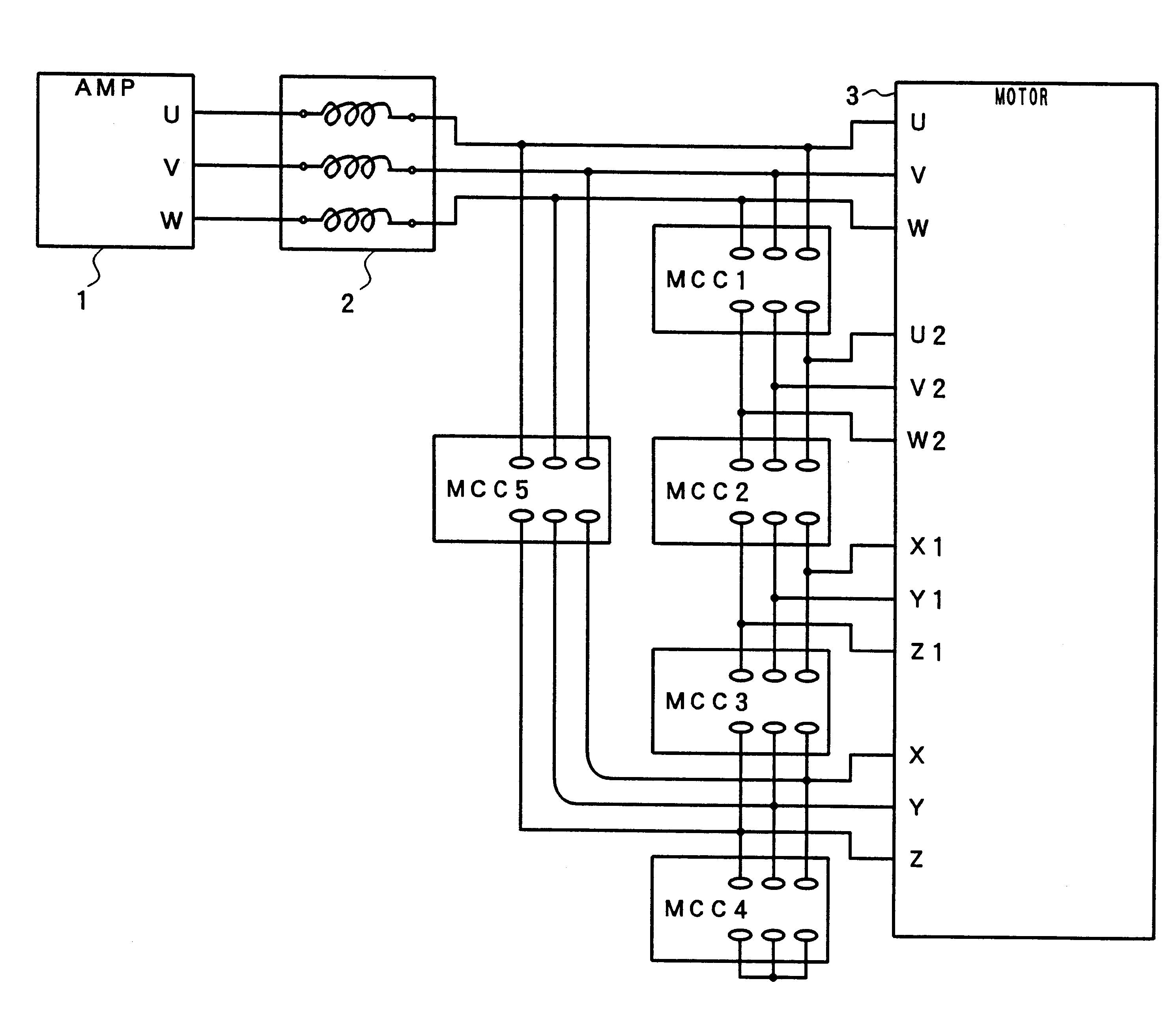
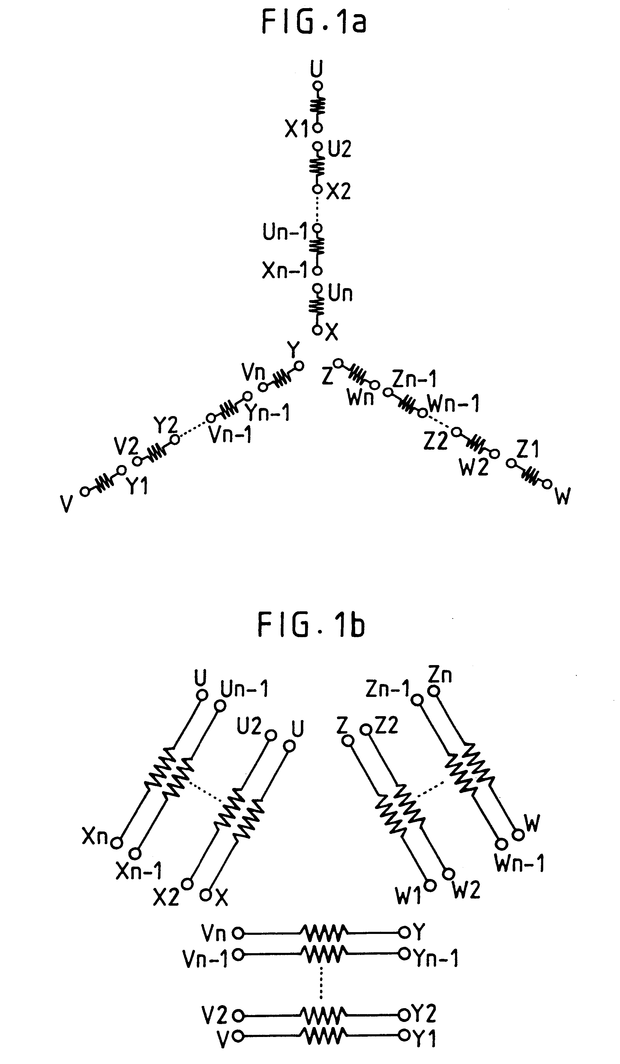
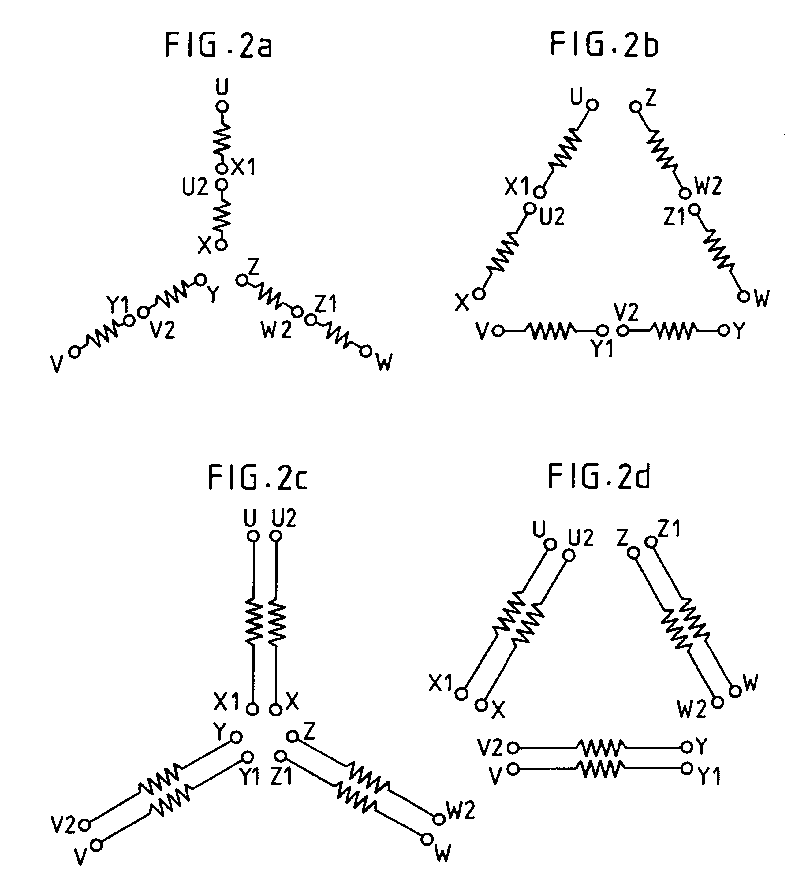
FIG. 1 is an illustration for explaining winding formations in an induction motor according to the present invention. In the present invention, each of three windings for three phases of alternating current is composed of n pieces (n is 2 or larger) of winding components having the same number of turns. When high power is needed with high speed rotation, a Y-connection is formed in which winding components for each phase are all connected in series as shown in FIG. 1a. (This formation will be referred to as "low speed winding formation.) When large torque is needed with low speed rotation, a .DELTA.-connection is formed in which winding components for each phase are all connected in parallel as shown in FIG. 1b. (This formation will be referred to as "high speed winding formation.)

It is to be noted that in FIG. 1, terminals provided at one-side ends of first winding components of three windings for three phases U, V, W are denoted by U, V, W, terminals provided at the other ends of ...


PUM


Abstract

An induction motor capable of obtaining a high power characteristic in a wide range without producing induced voltage. A winding for each phase is composed of a plurality of winding components having the same number of turns. When high torque is needed with low speed rotation, a Y-connection in which winding components for each phase are connected in series is formed as shown in FIG. 2a. For medium low speed rotation, a DELTA-connection in which winding components for each phase are connected in series is formed as shown in FIG. 2b. For medium high speed rotation, a Y-connection in which winding components for each phase are connected in parallel is formed as shown in FIG. 2c. For high speed rotation, a alpha-connection in which winding components for each phase are connected in parallel is formed as shown in FIG. 2d. Using the entire winding for each phase, the number of turns is decreased stage by stage to switch from low speed rotation to high speed rotation. Since there is no unused part of windings, there is no problem of induced voltage. A fall in power at the time of switching the winding formation can be restrained, so that a high power characteristic can be obtained in a wide range.

Description

The present invention relates to an induction motor driven by a three-phase alternating current supply, and more specifically to an induction motor suitable as a spindle motor for driving a spindle of a machine tool.A method of changing characteristics of a motor by changing formation of windings of the motor is conventionally known. FIGS. 6a and 6b show a method of changing characteristics of a motor by connecting windings of the motor as a Y-connection or a .DELTA.-connection. The larger number of turns the winding for each phase has, the larger torque can be produced with low speed rotation. Therefore, when large torque is needed with low speed rotation, the Y-connection (in which terminals X, Y, Z are connected together while power lines of three phases are connected to terminals U, V, W, respectively) as shown in FIG. 6a is selected. (This formation will be referred to as "low speed winding formation".) When high speed rotation is needed, the .DELTA.-connection (in which termin...

Claims


Application Information

Patent Timeline
IPC IPC(8): H02K17/02H02K17/14H02P23/00H02P23/07H02P25/10
CPCH02K17/14
Inventor NAKAMURA, KOSEIMASUYA, MICHIMAEDA, HISASHIUEMURA, SHINPEI
Owner FANUC LTD
Why Eureka
Try Eureka