Eureka AIR delivers breakthrough ideas for toughest innovation challenges, trusted by R&D personnel around the world.

Method for the control of an electronic circuit and control unit for its implementation

Inactive Publication Date: 2002-02-12
STMICROELECTRONICS SRL
View PDF16 Cites 2 Cited by
  • Summary
  • Abstract
  • Description
  • Claims
  • Application Information

AI Technical Summary

Problems solved by technology

It is known that the devising, designing and manufacture of a circuit of this kind is very costly.
However, it may happen that an existing integrated circuit or a functional block available in a library of drawings, while it corresponds functionally to the specifications of a new circuit to be designed, cannot be used again in an identical form within the framework of a new application.
Those skilled in the art will then be required to substantially modify the earlier circuit or the available functional block which, in practice, takes up almost as much time and is almost as expensive as developing a completely new circuit.
Now these costs may weigh very heavily in the cost of manufacture of a new integrated circuit especially if the quantities to be produced are too small to enable these costs to be recouped in the long term.

Method used


Image

  • Method for the control of an electronic circuit and control unit for its implementation
  • Method for the control of an electronic circuit and control unit for its implementation
  • Method for the control of an electronic circuit and control unit for its implementation

Examples


Embodiment Construction

The invention can be applied to the designing of electronic systems, especially systems that incorporate digital electronic circuits.

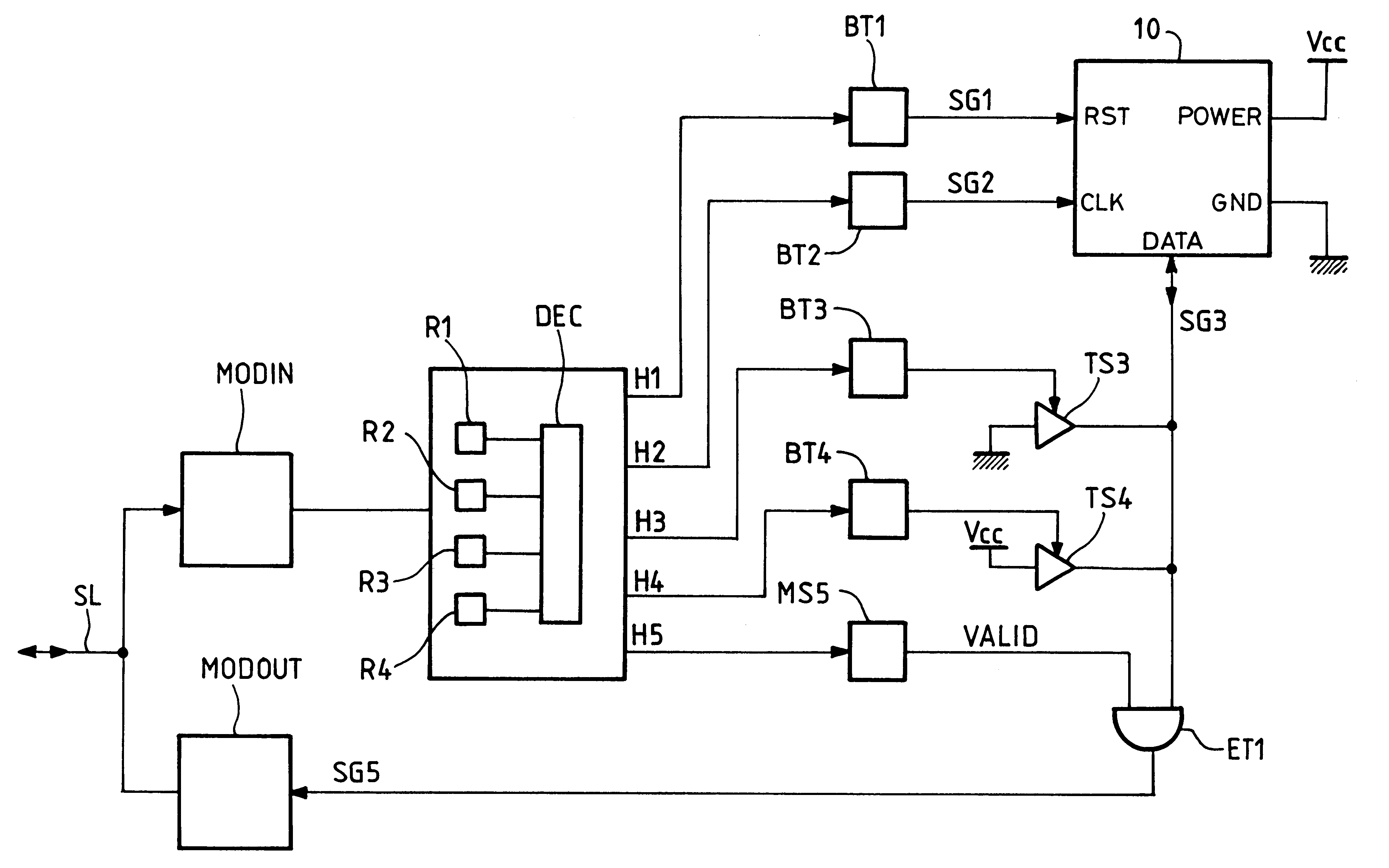
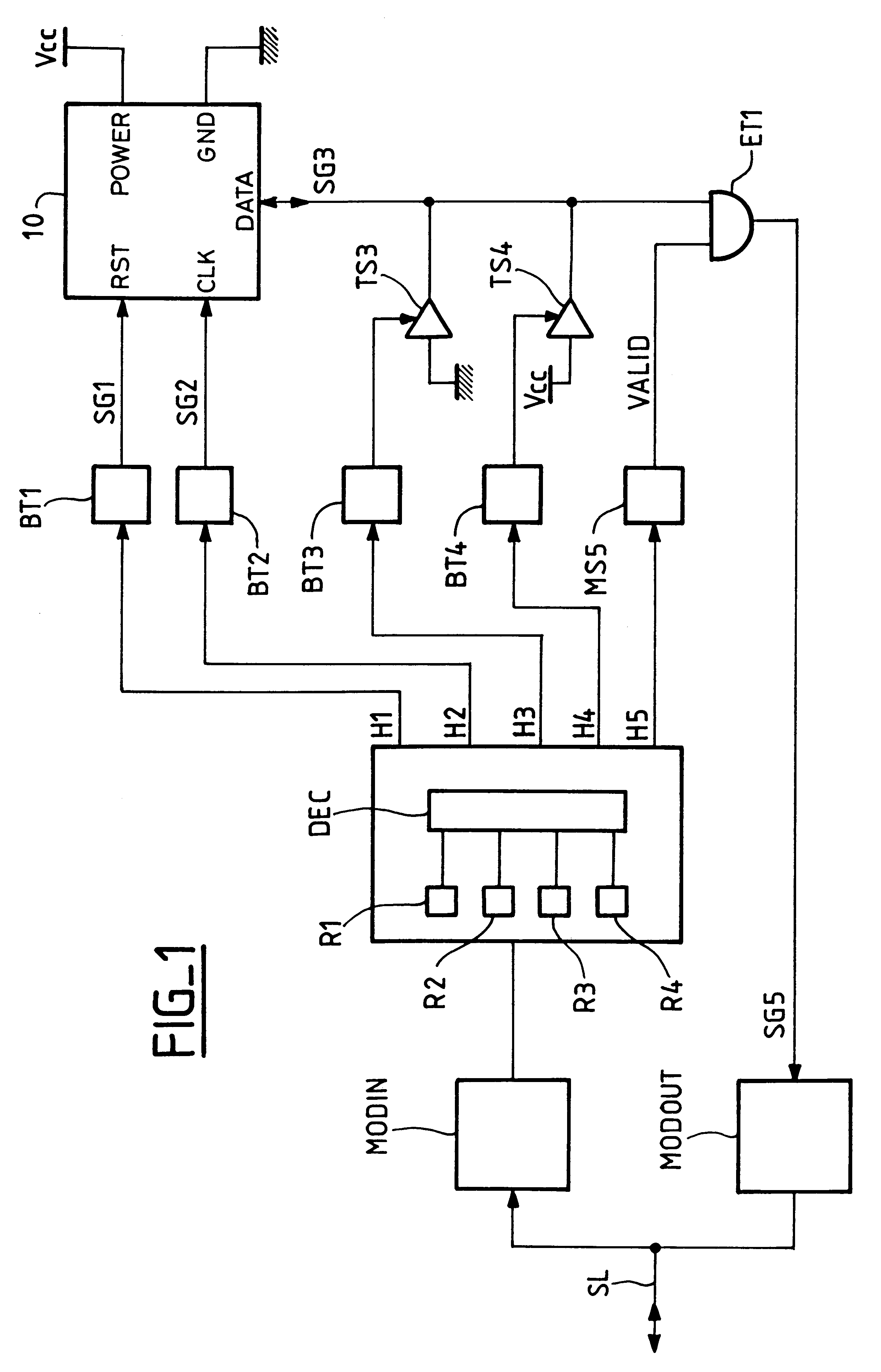
FIG. 1 shows a possible embodiment of a control or management unit according to the principles of the invention. This control unit is positioned between, first, a means for the serial transmission of data, herein represented by a line SL and, secondly, an electronic circuit 10 such as a telephone card memory.

The line SL may directly be a two-way data transfer line which, as the case may be but not necessarily, carries out a two-way transfer of data. In particular, it may be a wire link (made of copper) or an optical fiber. It may also be a link to an antenna, preferably a transceiver antenna for the serial transfer of data by wireless means, especially in the radiofrequency band (RF link).

An embodiment of the invention is a telephone card memory which, according to a French standard, is controlled (or managed) from the exterior through a plurality of c...


PUM


Abstract

A method for the control of an electronic circuit of the type includes at least one access pin to receive and / or deliver control signals, includes the generation, in a control unit, of control signals from data elements received serially through a data transfer input / output device. The method also includes the following steps: (1) extracting a control word included in the data received serially; and (2) decoding the control word extracted in the previous step in order to perform an operation, as a function of the value of the control word, thus modifying the logic state of at least one control signal. A control unit for accomplishing the foregoing steps includes a circuit for the extraction of a control word included in data elements received serially through a means for the serial transfer of data in the electronic circuit; a circuit for the decoding of said control word; and two or more of flip-flop circuits controlled by activation signals generated by the decoding circuit, the logic state of the output of the flip-flop circuits directly or indirectly determining the logic state of the control signals generated by the control unit.

Description

This application is based on and claims the benefit of priority of the prior French Patent Application No. 9716193 filed on Dec. 19, 1997, the contents of which are hereby incorporated by reference.1. Field of the InventionThe present invention relates to a method for the control of an electronic circuit of the type comprising at least one access pin to receive and / or deliver control signals as well as a control unit for the implementation of said method.2. Discussion of the Related ArtIt is known that the devising, designing and manufacture of a circuit of this kind is very costly. First of all, the circuit has to be defined from a functional viewpoint. Then it has to be simulated by means of computer-assisted design software. Then, it is necessary to prepare the pattern of the masks needed to make the circuit physically on an integrated circuit substrate of silicon. Finally, it still has to be tested once it has been integrated into a plastic package.This is why the manufacturers ...

Claims


Application Information

Patent Timeline
IPC IPC(8): G06F13/42G11C5/06
CPCG11C5/066G06F13/4291
Inventor GAULTIER, JEAN-MARIE
Owner STMICROELECTRONICS SRL
Why Eureka
Eureka Blog
Learn More