
System for exhaust gas purification

a technology of exhaust gas and purification system, which is applied in the direction of physical/chemical process catalysts, other chemical processes, separation processes, etc., can solve the problems of slow temperature elevation of hc adsorbent, low purification ability, and large amount of hc discharged from the engin

Inactive Publication Date: 2002-02-26
NGK INSULATORS LTD
View PDF11 Cites 8 Cited by
  • Summary
  • Abstract
  • Description
  • Claims
  • Application Information

AI Technical Summary

Problems solved by technology

During the cold start of engine when the temperature of exhaust gas from engine is low, the catalyst disposed in exhaust pipe of engine does not reach its light-off temperature and has a low purification ability.
Moreover, during this period, as compared with the period of continuous operation of engine, a large amount of HC is discharged from the engine.
As a result, the HC discharged during the cold start occupies a large proportion of the total harmful substances discharged from the engine and needs to be removed.
In this apparatus, the temperature elevation of the HC adsorbent is slowed because the three-way catalyst provided upstream of the HC adsorbent absorbs the heat of exhaust gas and thereby the gas temperature at the adsorbent inlet is kept low for a relatively long time.
However, they have had a problem in that they have insufficient heat resistance and easily undergo thermal deterioration.
Further, the technique disclosed in Japanese Patent Application Kokai (Laid-Open) No. 5-59942 are unable, at times, to sufficiently exhibit the intended effect of slowing the temperature elevation of HC adsorbent, because no consideration is made to the volume or heat capacity of the three-way catalyst provided upstream of the HC adsorbent.
When the loaded carrier has a total volume of smaller than 0.6 l, the thermal load of the adsorbent is not sufficiently reduced and the thermal deterioration of the adsorbent cannot be suppressed effectively.
Conversely, when the diameter of the blowing-through hole is too small, the warm-up of the catalyst provided downstream of the adsorbent or the loaded carrier is insufficient.

Method used


Image

  • System for exhaust gas purification
  • System for exhaust gas purification
  • System for exhaust gas purification

Examples


Embodiment Construction

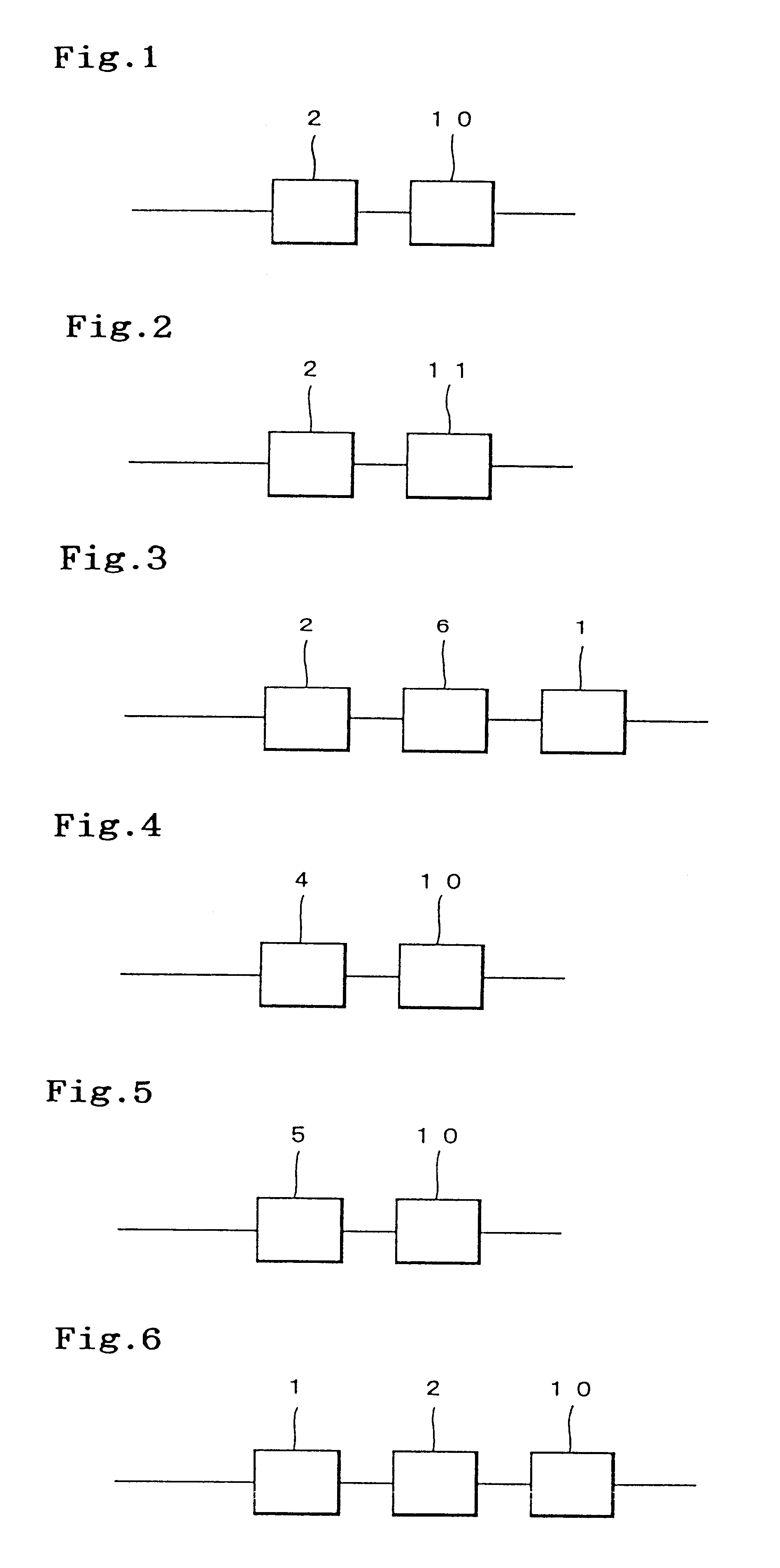
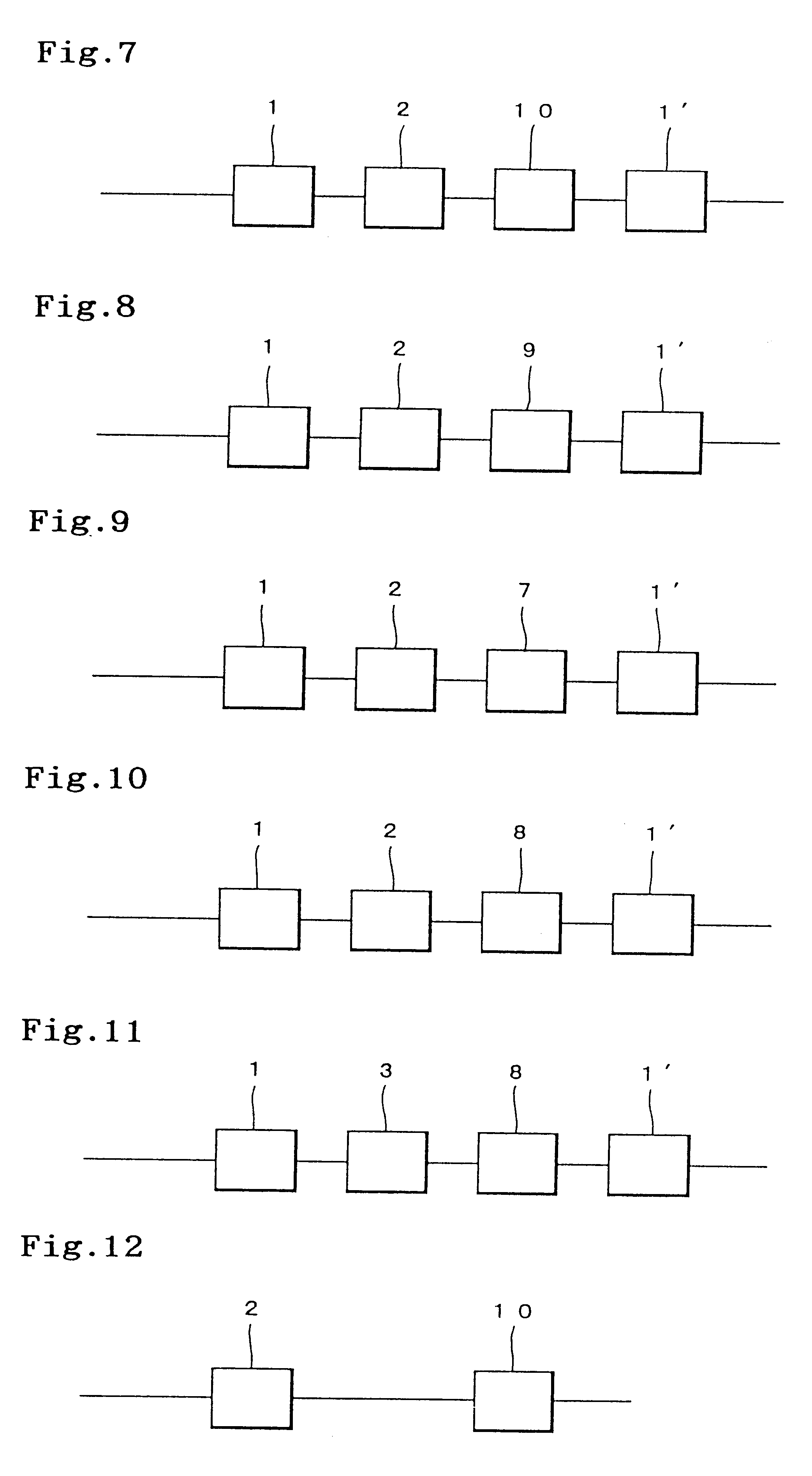
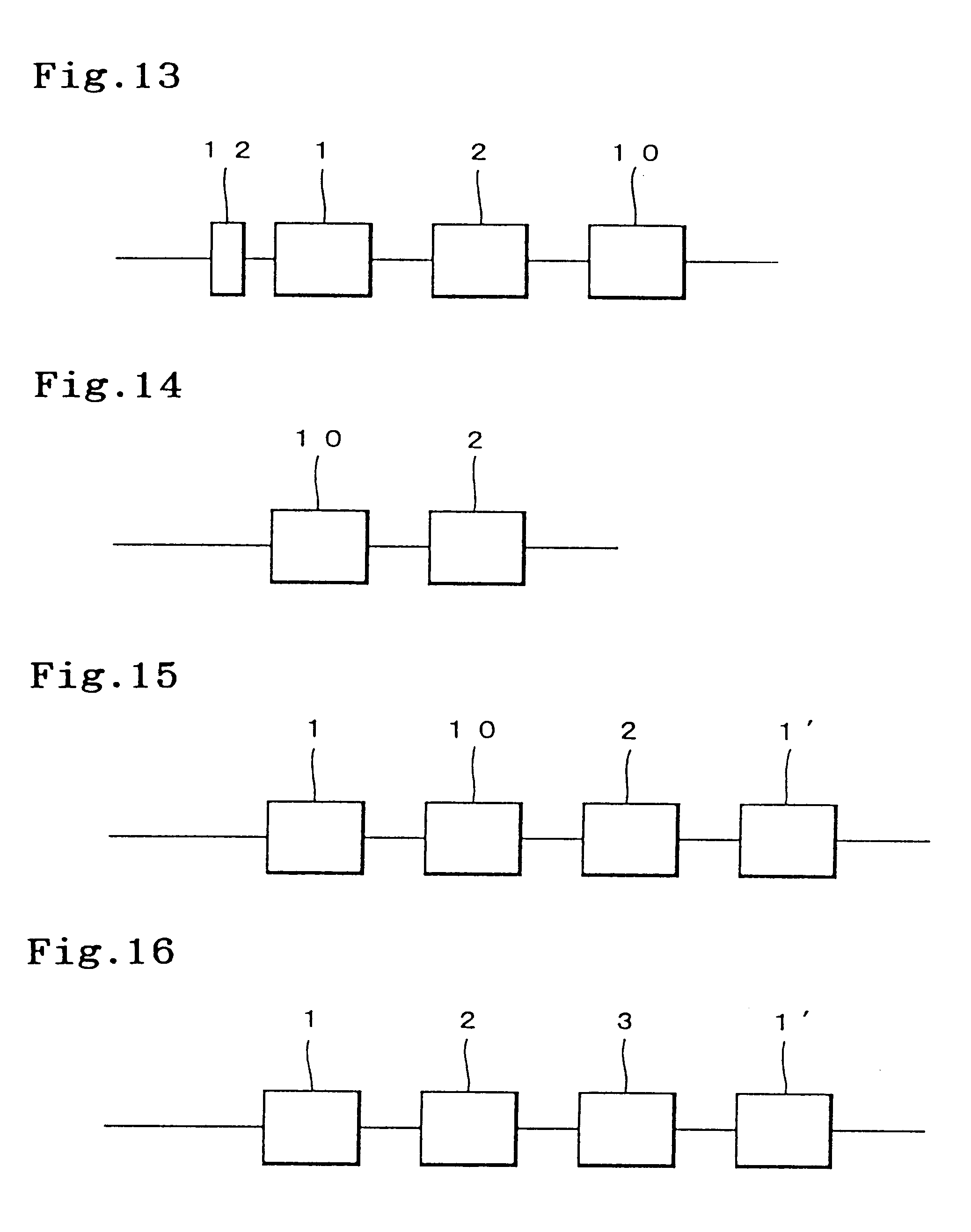
using system XIII, adsorbent D5 was cooled during the FTP, by the water-cooling device provided between catalyst A2 and adsorbent D5.

In all of Examples and Comparative Examples, secondary air was introduced into the systems. Except in Example 14, secondary air was introduced at a rate of 100 l / min for 0 to 100 seconds from the engine start and at a rate of 50 l / min for 100 to 250 seconds from the engine start, from an exhaust pipe position of 200 mm from the engine exhaust port. In Example 14, secondary air was introduced at a rate of 100 l / min for 0 to 100 seconds from the engine start from an exhaust pipe position of 200 mm from the engine exhaust port and at a rate of 50 l / min for 100 to 250 seconds from the engine start from between catalyst A2 and adsorbent D5.

After the FTP, a cylindrical sample (1 in. in diameter and 2 in. in length) was cut out from each adsorbent using an ion-containing zeolite (i.e. either of D1to D6), of each system and measured for HC adsorptivity as foll...


PUM

PropertyMeasurementUnit
total volumeaaaaaaaaaa
molar ratioaaaaaaaaaa
temperaturesaaaaaaaaaa

Abstract

A system for exhaust gas purification disposed in the exhaust pipe of an internal combustion engine, includes an adsorbent formed by loading, on a monolithic carrier, (1) a zeolite containing at least one kind of ion of an element having an electronegativity of 1.40 or more and (2) a catalyst material formed by loading at least one kind of noble metal selected from Pt, Pd and Rh on a heat-resistant inorganic oxide, and at least one loaded carrier formed by loading, on a monolithic carrier, a catalyst component having a purifiability for the harmful substances present in the exhaust gas emitted from the engine and / or an adsorbent component having an adsorptivity for the hydrocarbons also present in the exhaust gas, the loaded carrier being provided upstream of the adsorbent in the flow direction of the exhaust gas and having a total volume of 0.6 l or more. In this system for exhaust gas purification, the thermal deterioration of the adsorbent is reduced because there is used an adsorbent of higher HC desorption start temperature and because the thermal load applied to the adsorbent is decreased by the use of a particular means.

Description

(1) Field of the InventionThe present invention relates to a system for exhaust gas purification, capable of effectively purifying the harmful substances present in the exhaust gas emitted from an internal combustion engine, particularly the hydrocarbons discharged from the engine in a large amount during the cold start.(2) Description of Related ArtActive researches and developments have heretofore been made on systems for exhaust gas purification, used for purifying the harmful substances present in exhaust gas from automobile engine, such as nitrogen oxides (NO.sub.x), carbon monoxide (CO), hydrocarbons (HC) and the like. In recent years, as the regulation on exhaust gas has become stricter, the purification of HC during engine start (cold start) has become an important technical task.The reason is as follows. During the cold start of engine when the temperature of exhaust gas from engine is low, the catalyst disposed in exhaust pipe of engine does not reach its light-off tempera...

Claims


Application Information

Patent Timeline
Patent Type & Authority Patents(United States)
IPC IPC(8): B01D53/94F01N3/08F01N7/00F01N7/02F01N3/28B01D53/34B01D53/72B01J20/18B01J23/40F01N13/02
CPCB01D53/945B01D2255/912F01N3/0814F01N3/0835F01N13/009Y02T10/12
Inventor NODA, NAOMISHIBAGAKI, YUKINARITAKAHASHI, AKIRAMIZUNO, HIROSHIGE
Owner NGK INSULATORS LTD
Learn More