Graphical user interface

a user interface and graphical technology, applied in the field of graphical user interfaces, can solve the problems of affecting the operation of windows, affecting the user experience, and becoming more graphic intensive,

Inactive Publication Date: 2002-03-05
SUN MICROSYSTEMS INC
View PDF14 Cites 122 Cited by
  • Summary
  • Abstract
  • Description
  • Claims
  • Application Information

AI Technical Summary

Benefits of technology

It is still another object of the present invention to make it easier to access windows or groupings of windows in computing system with a graphic user interface.
It is yet another object of the present invention to enable users to rapidly navigate through windows or computational objects.
It is still another object of the present invention to make it easy to perform certain computer functions without requiring use of a keyboard or mouse.
According to the invention, a computerized system, (comprising either a method, computer programming, and / or a computer operating system) provides an improved graphical user interface. Stated roughly, this system defines a view space in which graphical user interface windows generated by separate computer processes can be selectively located by a user. The view space has a plurality of discrete portions each of which is large enough to hold a plurality of user interface windows. The system enables a user to selectively associate one or more of the view space portions with each of one or more physical locations external to, and not physically connected to, the computing apparatus used in the method. The system enables a user to selectively locate a variable number of user interface windows in each of the view space portions associated with a physical locations, including enabling the user to selectively move windows between such view space portions. The system detects when a user motions toward a given one of the physical locations; and it responds to a detection that the user has so motioned toward a given physical location by presenting a visual display to the user which shows the given view space portion associated with the given physical location, together with any window located in the given view space portion.

Problems solved by technology

Application programs have taken advantage of this increased computing power, and as a result, have become more graphic intensive.
The size of standard computer terminals (e.g., a 19 inch monitor) has become a limiting factor in presenting processed information to the user.
The window operating environment, although useful, is often frustrating to operate.
The user is required to spend an inordinate amount of time moving, resizing, and opening and closing various windows and icons on the display space.
The opening and closing of a window is often slow.
It is also difficult to manipulate information within windows.
The physical size of the display terminal limits the size of each window, the number of windows that can be displayed at a given time, and, in the case of graphic intensive applications, is often too small to display an image of an object in its entirety.
These extra-large monitors do increase the display capabilities of the computer to some degree, but the problems outlined above are still present.
These monitors are also prohibitively expensive to build and difficult to ship to customers.
This monitor is clearly impractical for standard desktop computers.
While this can be useful, it requires the user to perform mouse operations to access different portions of the view space, which take time and which can be difficult if his computer does not have mouse or if he, or his hands, are not in situation in which using a mouse is convenient.
In the mobile computing made possible by smaller computers and displays, traditional computer mice are often difficult and awkward to use, and other methods of selecting and interacting with computing objects are desirable.

Method used


Image

  • Graphical user interface
  • Graphical user interface
  • Graphical user interface

Examples


Embodiment Construction

I. Continuous View Space

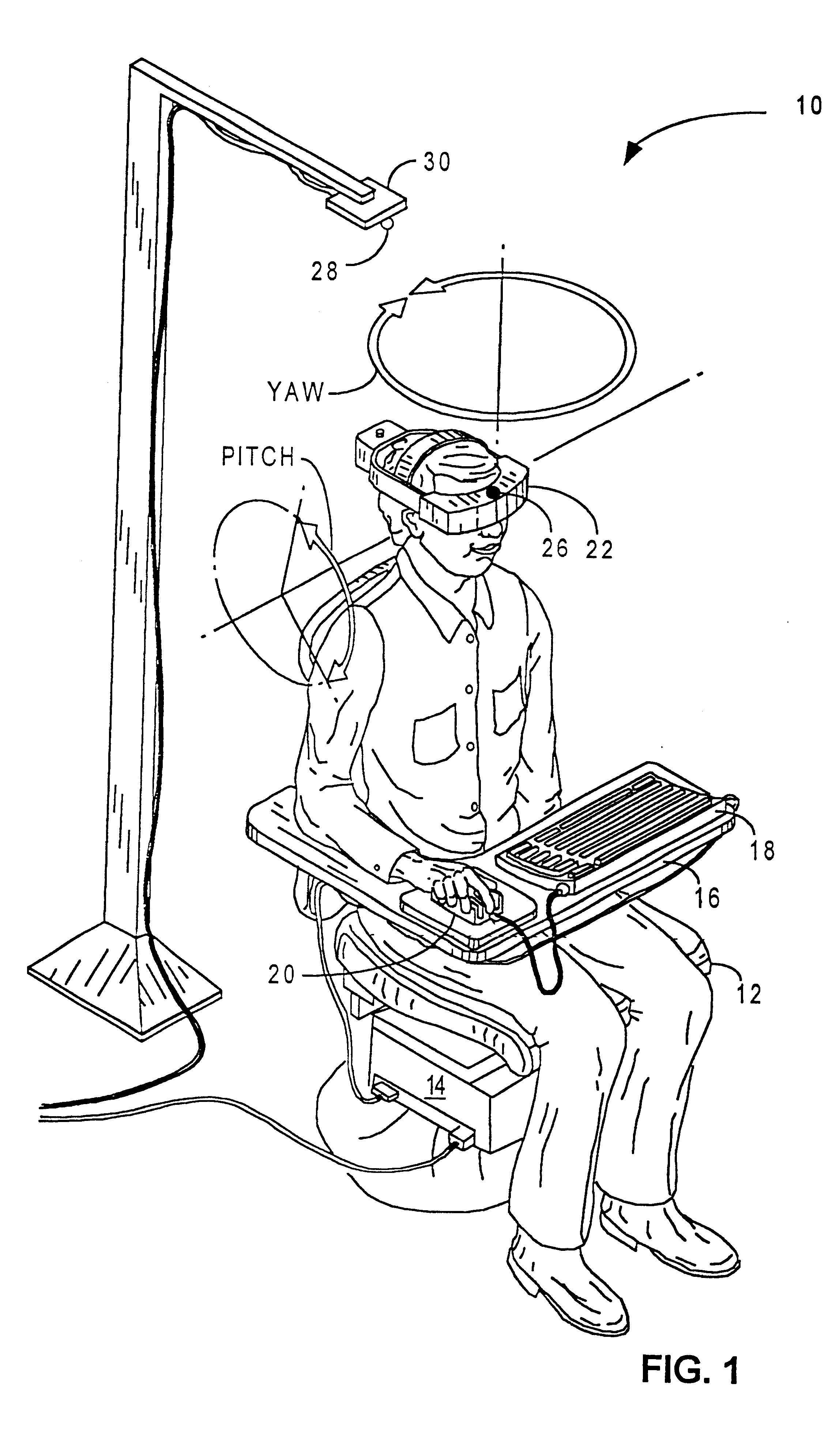
Referring to FIG. 1, a computer operator using the video display system of the present invention is shown. The video display system 10 includes a swiveling chair 12, a computer 14 mounted at the base of the chair 12, a platform 16 for supporting computer peripheral devices such as a keyboard 18 and a mouse 20, a head mounted display 22 and a position sensor 24 (housed inside computer 14), including a transmitter 26 mechanically coupled to the head mounted display 22 and a receiver 28 mechanically connected to a stationary reference point 30. The reference point can be located above the user's head as illustrated in FIG. 1, at the base of the chair 12, or any other stationary location in the vicinity of the video display system 10.

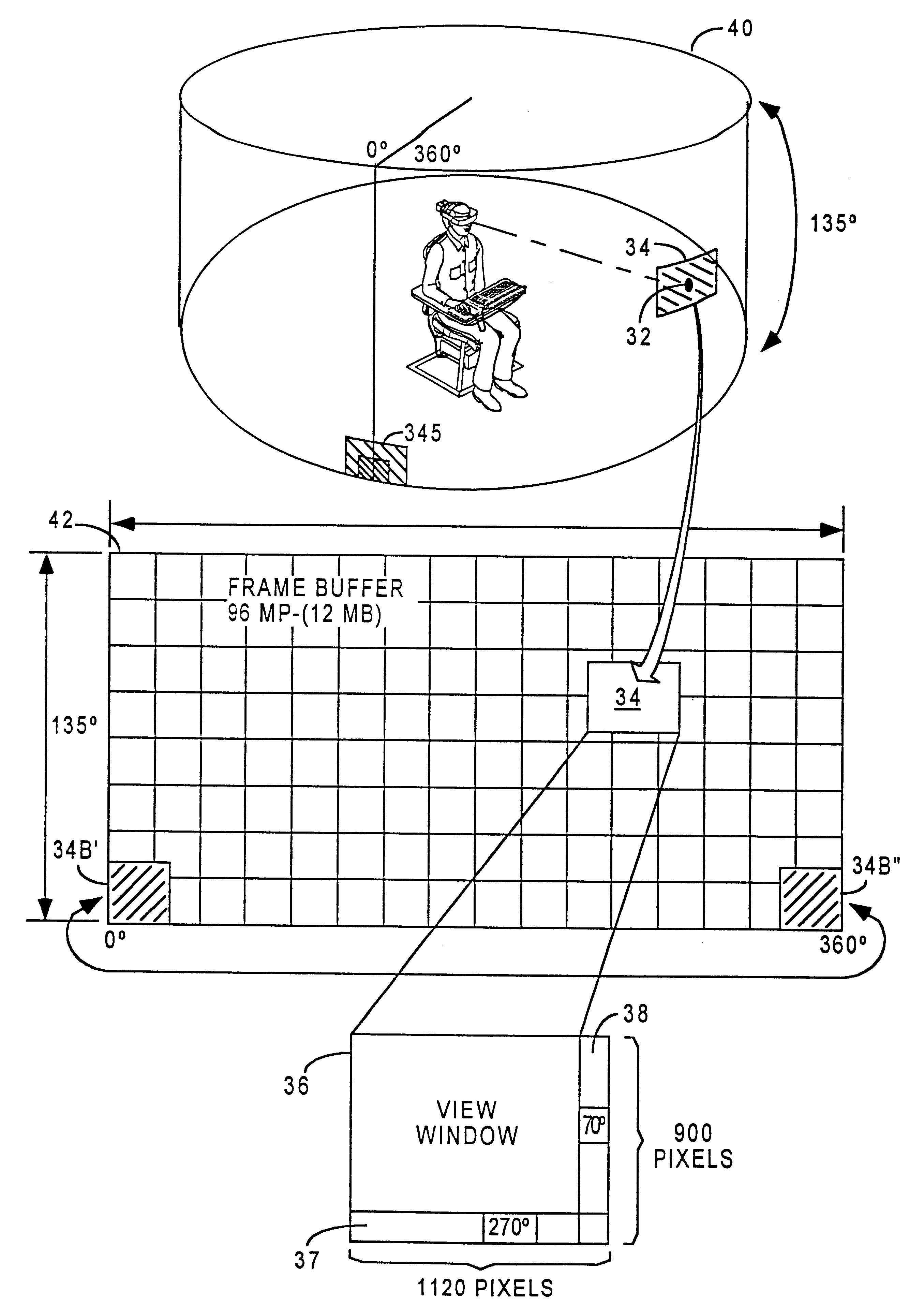
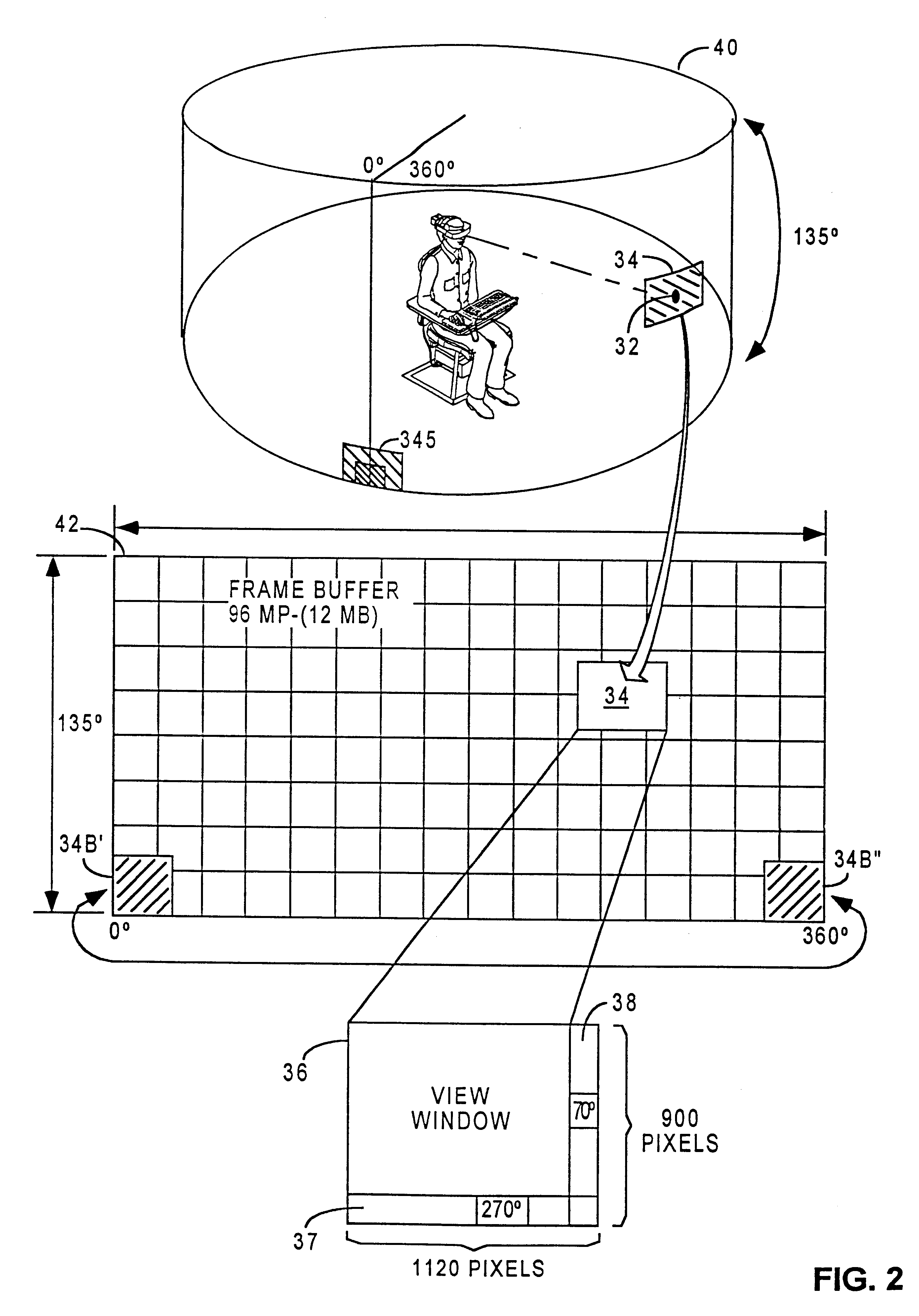
Referring to FIG. 2, the relationship between a frame buffer, a view port and a view window in a virtual view space in the video system 10 is illustrated. The virtual view space 40 is the total image area in the video display system ...


PUM


Abstract

A computer system provides an improved graphical user interface by defining a view space in which graphical user interface windows from separate computer processes can be selectively located by a user. This view space has a plurality of discrete portions each large enough to hold a plurality of such user interface windows. The system enables users to selectively associate view space portions with physical locations external to the system's computing apparatus. The system also enables users to selectively locate a variable number of the user interface windows in each of the view space portions associated with such a physical location, including enabling the user to selectively move windows between such view space portions. The system detects when a user motions toward a given physical locations and responds to such a detection by presenting a visual display showing the given view space portion associated with the given physical location, together with any user interface window located in the given view space portion. In some versions of the invention, the physical location can be defined by a global positioning system and the system can detect when a user moves into a location defined by such global positioning.

Description

1. Filed of the InventionThe present invention relates to an improved computer graphical user interface.2. Background of the InventionComputers have vastly increased their ability to process information. Many computers now include one or more powerful microprocessors. Multitasking operating systems have given the computer the ability to execute more than one application at a time. Application programs have taken advantage of this increased computing power, and as a result, have become more graphic intensive.The size of standard computer terminals (e.g., a 19 inch monitor) has become a limiting factor in presenting processed information to the user. A standard desktop computer now has the capability to inundate the display terminal of the computer with information. The computer industry has attempted several approaches to overcome this problem.The most common approach has been window based software. Windowing systems attempt to maximize the use of the screen space of a display termin...

Claims


Application Information

Patent Timeline
Patent Type & Authority Patents(United States)
IPC IPC(8): G06F3/00G06F3/01
CPCG06F3/011
Inventor REICHLEN, BRUCE A.
Owner SUN MICROSYSTEMS INC
Why Eureka
Try Eureka