Image-pickup apparatus and method for reading accumulated signal changes through transfer lines

a technology of transfer lines and image pickup, which is applied in the direction of television system scanning details, radio control devices, television systems, etc., can solve the problems of increasing the heating amount of the driving circuit, increasing the dissipation power of the image pickup apparatus, and increasing the noise of dark curren

Inactive Publication Date: 2002-03-12
NIKON CORP
View PDF8 Cites 18 Cited by
  • Summary
  • Abstract
  • Description
  • Claims
  • Application Information

AI Technical Summary

Problems solved by technology

For high-speed driving of this large capacity, a large driving current is necessary, which will result in increasing the dissipation power of the image-pickup apparatus.
Flow of the large driving current will increases heating amounts of the driving circuit, whi

Method used


Image

  • Image-pickup apparatus and method for reading accumulated signal changes through transfer lines
  • Image-pickup apparatus and method for reading accumulated signal changes through transfer lines
  • Image-pickup apparatus and method for reading accumulated signal changes through transfer lines

Examples


first embodiment

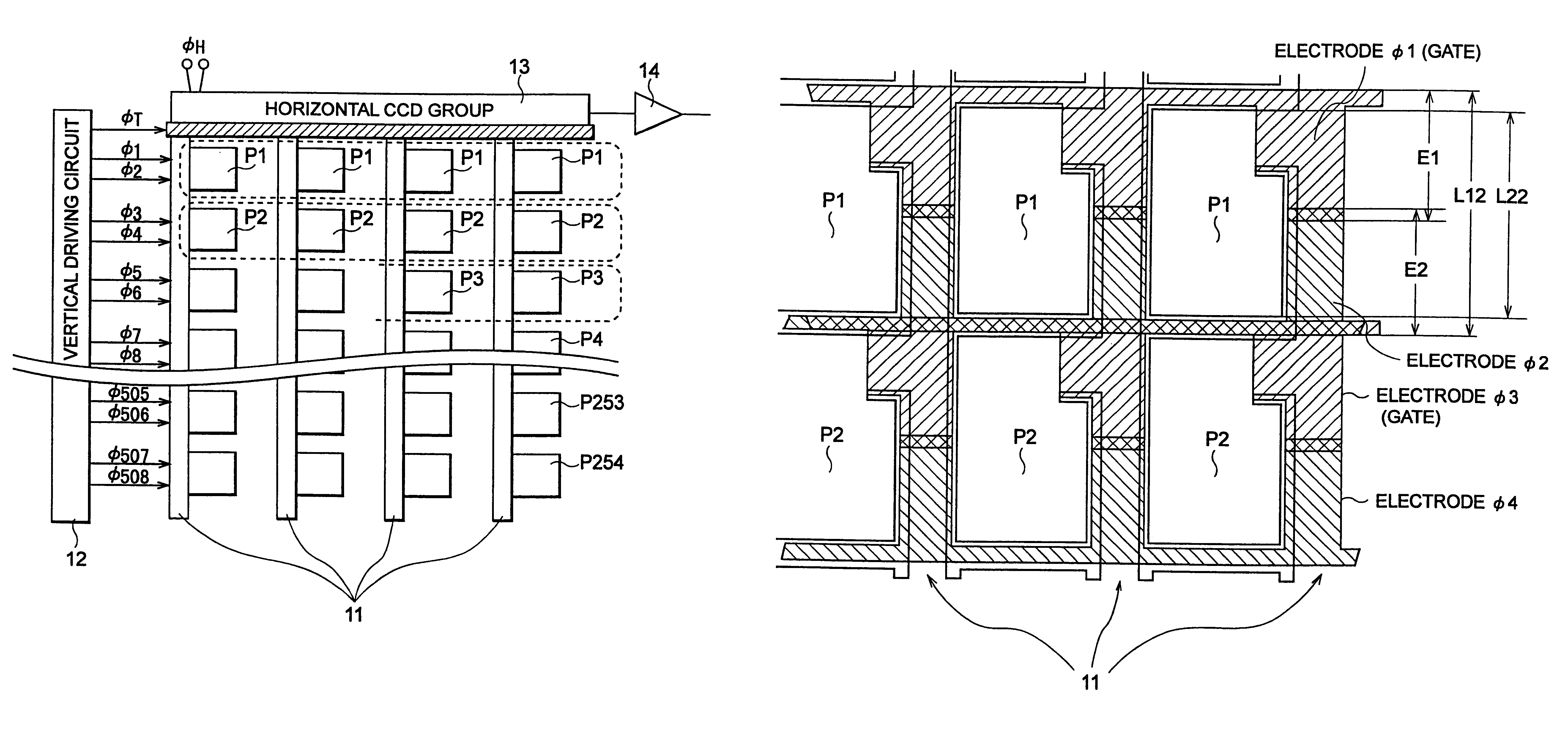
FIG. 4 is a conceptual drawing of the image-pickup apparatus according to the present invention. In this figure, the image-pickup apparatus has a plurality of photodetection portions 1 arrayed two-dimensionally on the image-pickup surface, a plurality of vertical transfer lines 2 for vertically transferring signal charges accumulated in the photodetection portions 1 and read every predetermined horizontal line out of the plurality of photodetection portions 1, and a horizontal transfer line 3 for horizontally transferring signal charges outputted from the vertical transfer line group 2. Particularly, this image-pickup apparatus further has a vertical driving control system 5 for establishing a plurality of potential wells 4 longer than a vertical width of a horizontal line, in the vertical transfer lines 2 and for successively moving the potential wells 4 in the vertical direction, and gate structures 6 for transferring signal charges accumulated in the photodetection portions 1 to ...

second embodiment

Next, FIG. 16 is a drawing to show a timing chart of the second embodiment of the image-pickup apparatus according to the present invention and FIG. 17 is a drawing for explaining the operation (the driving method) of the second embodiment of the image-pickup apparatus according to the present invention. Since the structure of the image-pickup apparatus of the second embodiment is the same as that of the image-pickup apparatus of the first embodiment (FIG. 5) described above, redundant description is omitted herein.

The operation (the driving method) of the second embodiment will be described below.

First, the vertical driving circuit 12 applies the intermediate voltage VM to each group of 6-7 electrodes on each of the vertical transfer lines 11, thereby establishing a plurality of potential wells having the length of 3-3.5 horizontal lines.

Next, the vertical driving circuit 12 applies 8-phase driving pulses to the electrodes .phi.1-.phi.508 on the vertical transfer lines 11 only duri...

third embodiment

FIG. 18 is a conceptual drawing of the third embodiment of the image-pickup apparatus according to the present invention.

In this image-pickup apparatus of the third embodiment the vertical driving control system 5 establishes in each vertical transfer line 11 a main potential well 4 in which a signal charge being a transferred object is present, and an auxiliary potential well 4a, subsequent to the main potential well 4, for transferring a leak of the signal charge. The apparatus is characterized in that the vertical driving control system 5 outputs (or adds) to each horizontal transfer line 3 a signal charge in the main potential well 4 and a leak thereof collected in the auxiliary potential well 4a subsequent to the main potential well 4.

This auxiliary potential well 4a is formed in order to collect the transfer leak from the preceding main potential well 4, which can surely prevent such a malfunction that the transfer leak of signal charge is mixed in another signal charge.

In thi...


PUM


Abstract

The present invention concerns an image-pickup apparatus and a method for driving the same, adapted for reading signal charges accumulated in a plurality of photodetection portions provided on a predetermined plane through vertical transfer lines and a horizontal transfer line. The image-pickup apparatus has the structure for establishing potential wells having a length not smaller than a vertical width of a horizontal line, in the vertical transfer lines, thereby permitting the horizontal width of the vertical transfer lines to be decreased. Since the image-pickup apparatus has the structure for establishing the plurality of potential wells having signal charges in the vertical transfer lines at a predetermined time, the signal charges can be transferred efficiently with keeping low driving speed of the vertical transfer lines.

Description

1. Field of the InventionThe present invention relates to an image-pickup apparatus and a method for driving the same, adapted for reading signal charges accumulated in a plurality of photodetection portions provided on a predetermined plane, through vertical transfer lines and a horizontal transfer line, which extend perpendicular to each other on the plane.2. Related Background ArtThe conventional electronic cameras and video cameras are equipped with an image-pickup apparatus, for example, composed of CCD image sensing devices or MOS image sensing devices. Some conventional examples of the image-pickup apparatus of this type will be described.FIG. 1 is a drawing to show the structure of a conventional image-pickup apparatus of a progressive scan type (the first conventional example).In FIG. 1, the image-pickup apparatus of the first conventional example has photodetection portions 51 of photodiodes or the like arrayed two-dimensionally on an image-pickup surface. Vertical transfe...

Claims


Application Information

Patent Timeline
IPC IPC(8): H01L27/148H04N5/335H04N3/15H04N5/341H04N5/353H04N5/359H04N5/361H04N5/372H04N5/376
CPCH01L27/14843H04N5/335H04N3/155H04N25/73H04N25/00
Inventor AKAGAWA, KEIICHI
Owner NIKON CORP
Why Eureka
Try Eureka