After market LED taillight bulb

a taillight and aftermarket technology, applied in the direction of fixed installation, lighting and heating equipment, lighting support devices, etc., can solve the problems of not being able to achieve the desired appearance of the tinted cover of the taillight assembly, the size and bulkiness of the prior art light assembly, and the inability to produce one hue of white light, etc., to achieve the effect of enhancing the life of the light assembly, reducing the cost of assembly, and reducing the cost of production

Inactive Publication Date: 2002-03-19
AMERICAN PROD INC
View PDF7 Cites 71 Cited by
  • Summary
  • Abstract
  • Description
  • Claims
  • Application Information

AI Technical Summary

Benefits of technology

Since the electrical components of the circuit board are positioned within an enclosed space, the electrical components arc thereby more protected from exposure to the elements and, thus, the life of the light assembly is enhanced. Moreover, since the light source is an LED, a high intensity red light source is thereby provided which can provide red illumination suitable for, among other things, brake lights, without requiring the same power as ordinary incandescent lights which results in a longer lasting, brighter light. Moreover, the use of red LED lights can also permit the use of clear tinted replacement taillight assemblies instead of red tinted assemblies.
In another aspect of the present invention, the LED assembly

Problems solved by technology

Prior art light assemblies are often large and bulky in nature, especially in the case where a reflector is used to direct and intensify the light source.
Another limitation of existing incandescent light sources employing evacuated glass bulbs with tungsten filaments or higher intensity halogen-based light sources is that they typically only produce one hue of white light.
However, the appearance of the tinted covers of tail light assemblies may not be a desired appearance by all vehicle owners, particularly if the tail light assembly requires significant amounts of red material.
This increases the overall size and cost of the tail light assembly as it requires multiple shades of light transmissive covers.
A further difficulty that occurs with existing tail light assemblies is that the assemblies can become dirty which inhibits the light transmissive properties of the cover.
With the particular example of a brake light, if the light transmissive cover becomes too dirty, the cover transmit less light which makes the brake lights harder to see by oncoming vehicles.
This problem i

Method used


Image

  • After market LED taillight bulb
  • After market LED taillight bulb
  • After market LED taillight bulb

Examples


Embodiment Construction

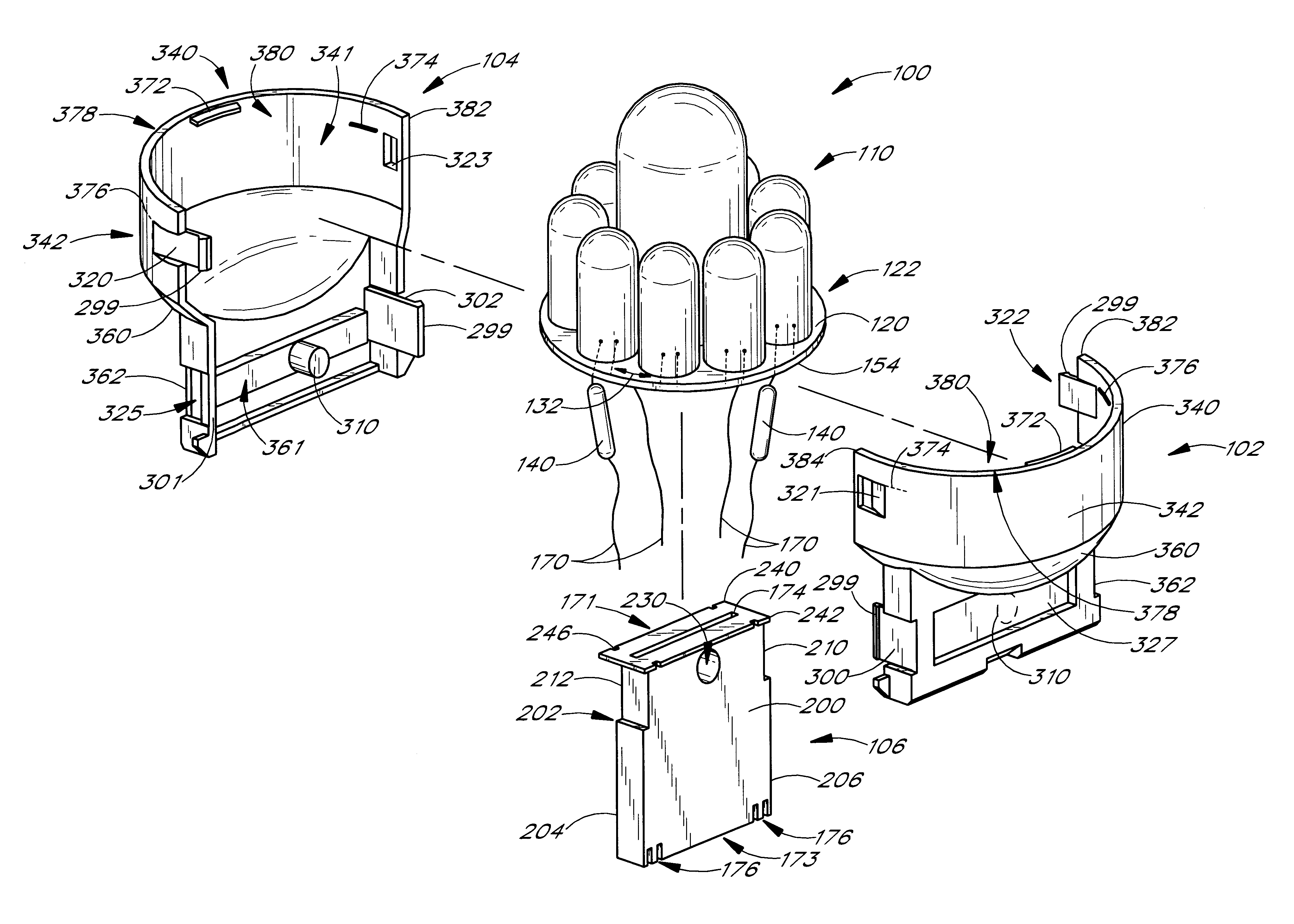
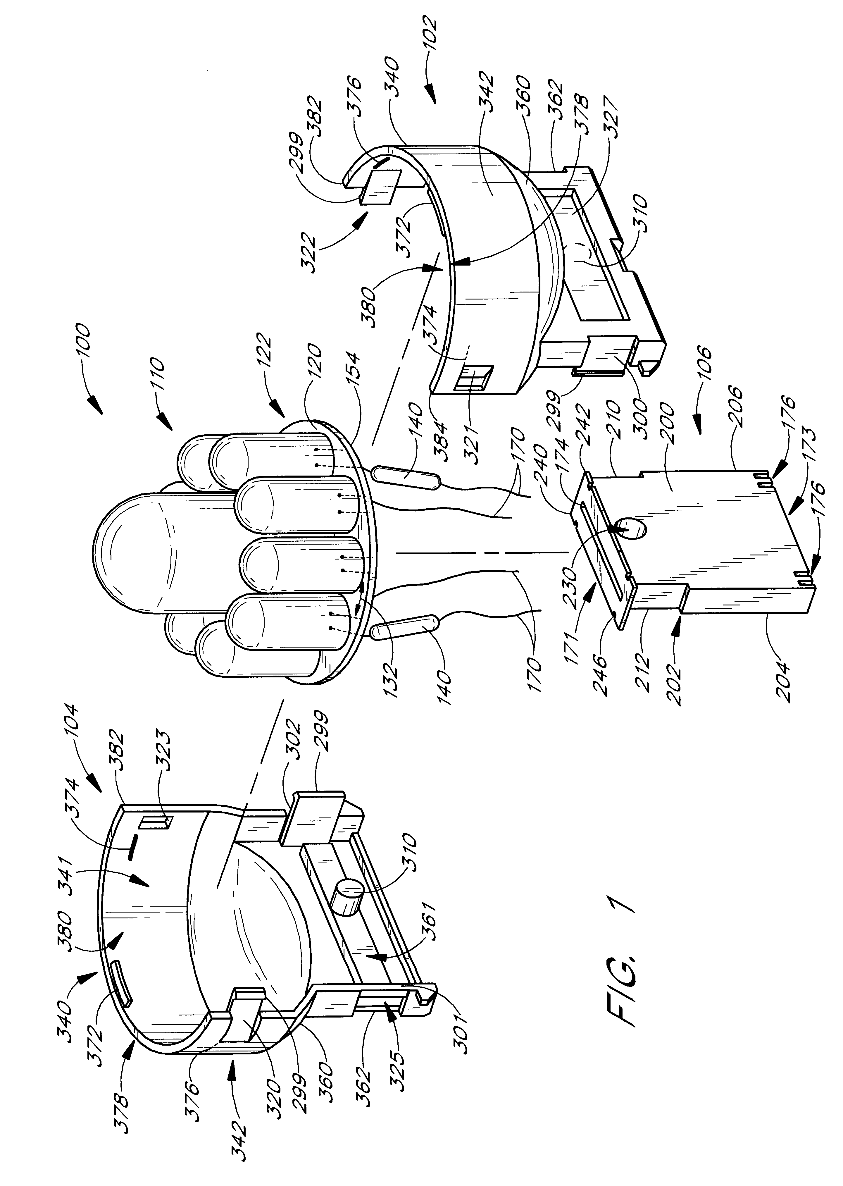
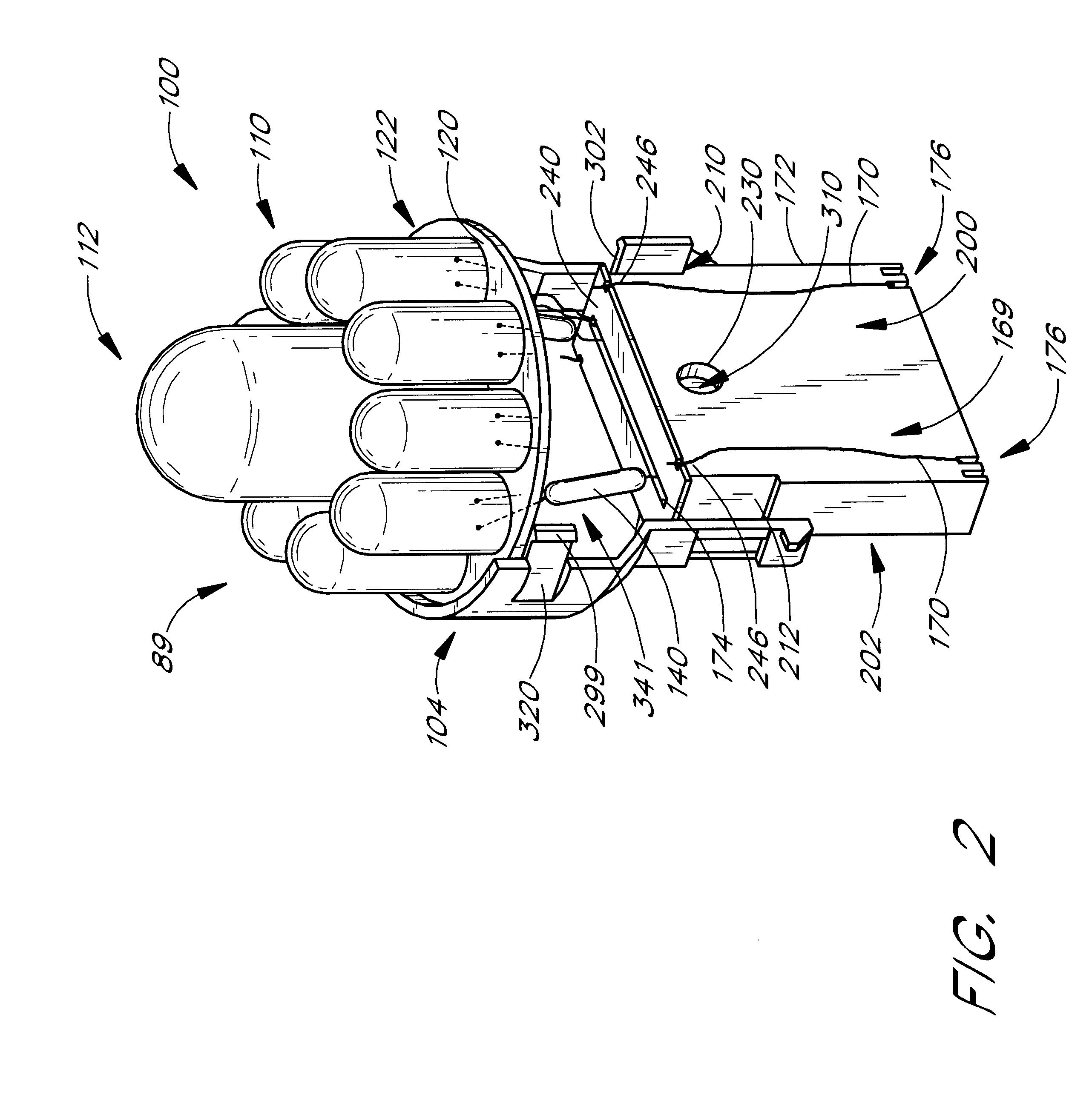
Reference will now be made to the drawings wherein like numerals refer to like parts throughout. FIG. 1 illustrates an exploded view of the LED assembly 100 with left 104 and right 102 housing members and a male plug member 106. The assembled light fixture 90 (shown in FIG. 3) is adapted to be mounted by removable attachment to a female plug member (not shown) such as might be found in taillight or turn indicator assembly in a vehicle. The male plug member 106 may be adapted to join with any of a number of female plug member configurations so as to be compatible with various makes and models of vehicles. The light assembly of the present invention as such, can therefore be used to replace stock incandescent light bulbs in these vehicles by quickly and easily removing the light assembly without modifying the existing components of the female plug member or light assembly housing of the vehicle.

While a particular plug and LED configuration is shown in the illustrated embodiment it sho...


PUM


Abstract

A light emitting diode (LED) assembly designed to be used in a light bulb mounting assembly in a vehicle, such as taillight or turn indicator assembly. The LED assembly having a plurality of LEDs mounted upon a single circuit board that may be arranged in numerous colors, patterns and shapes to give a distinctive look to the light generating assembly. The LED assembly is contained within a durable water and shock resistant structure with a compatible plug member to be used in conjunction with existing light bulb mounts present in the vehicle. The LED assembly can be used to easily replace existing incandescent light bulbs present in the vehicle and provide additional color and lighting patterns eliminating the need for tinted glass bulbs or light transmissive covers to generate variations in colored light.

Description

BACKGROUND OF THE INVENTION1. Field of the InventionThe present invention generally relates to light bulb assemblies for vehicles, and in particular, concerns taillight assembly for an automobile wherein a light emitting diode assembly is mounted within a durable water-resistant structure that is used in conjunction with existing light bulb mounts present in the automobile.2. Description of the Related ArtLight generating sources for automobiles typically comprise an assembly wherein an incandescent light bulb is mounted within a mounting apparatus further comprising a base, which may be reflective, and a light-transmissive cover, which may be tinted to produce a particular illuminated color. Prior art light assemblies are often large and bulky in nature, especially in the case where a reflector is used to direct and intensify the light source.Another limitation of existing incandescent light sources employing evacuated glass bulbs with tungsten filaments or higher intensity halogen...

Claims


Application Information

Patent Timeline
IPC IPC(8): F21S8/00F21K7/00F21S8/10F21V19/00F21K99/00
CPCF21S8/035F21S48/212F21S48/215F21K9/135F21K9/13Y10S362/80F21Y2101/02F21K9/23F21K9/232F21Y2115/10F21S43/14F21S43/195
Inventor HOROWITZ, BRIAN
Owner AMERICAN PROD INC
Why Eureka
Try Eureka