
Optically powered resonant tunneling device

Inactive Publication Date: 2002-03-19
RAYTHEON CO
View PDF5 Cites 8 Cited by
  • Summary
  • Abstract
  • Description
  • Claims
  • Application Information

AI Technical Summary

Problems solved by technology

Typically, field effect transistors, bipolar transistors, impact ionization diodes, and Gunn-effect diodes are used in microwave oscillators, but these devices have inherent frequency limitations due to their size which limits speed due to transit time effects.
However, resonant tunneling diode oscillator circuits are very difficult to electrically bias so that the bias circuitry does not resonate with the RTD and produce unwanted modes of oscillation.
However, this method still allows the parasitic resonances to occur in the power supply circuitry.
Therefore there remains the general problem of providing RTD-based circuits that oscillate at ultra high frequency while suppressing lower frequency oscillations.

Method used


Image

  • Optically powered resonant tunneling device
  • Optically powered resonant tunneling device
  • Optically powered resonant tunneling device

Examples


Embodiment Construction

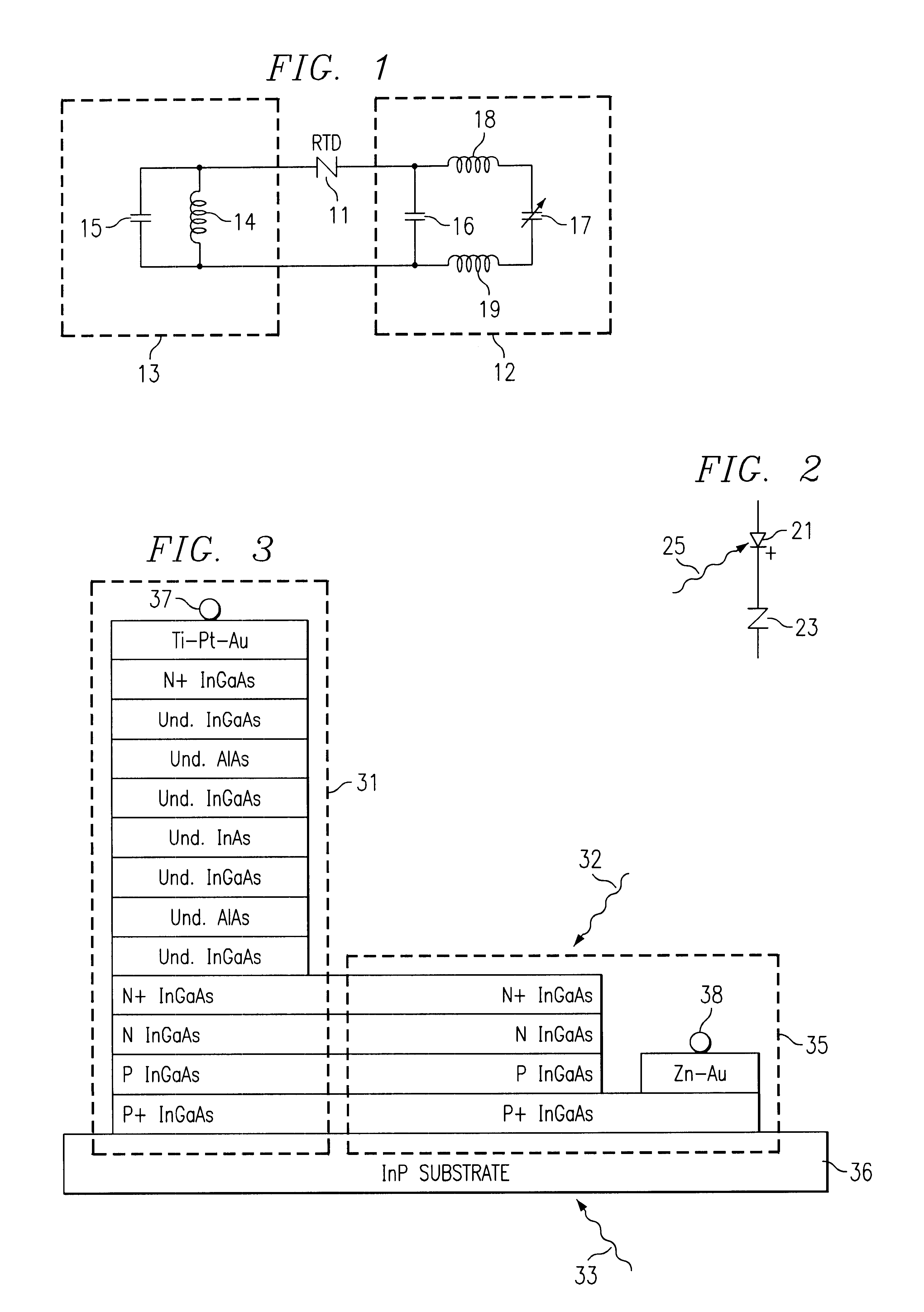
Resonant tunneling diodes have intrinsic electrical gain which allows them to be used in amplifiers and oscillators up to at least several hundreds of GHz. Referring to FIG. 1 a typical RTD-based oscillator 10 may contain RTD 11 with a power supply 12 and resonant circuit 13. Resonant circuit 13 may consist of an inductor 14 and capacitor 15 tuned to the desired radio frequency. The power supply 12 may consist of a RF bypass capacitor 16, a voltage source such as battery 17, and wires consisting of inductors 18 and 19 that connect the voltage source to the bypass capacitor, RTD, and tuned circuit. The RTD has electrical gain from zero frequency (dc) to an upper limit Fmax. Because the gain of the RTD tends to decrease with frequency, the lowest characteristic resonant frequency of the circuitry of oscillator 10 will tend to set the frequency of RTD oscillation. This is a special problem at high microwave frequencies where the RTD gain tends to roll off with increasing frequency. Due...


PUM


Abstract

An improved resonant tunneling device (RTD) oscillator is provided by supplying electrical power to the RTD device 23 using a photocell 21 and a light source 25 such that essentially no spurious resonances are possible.

Description

1. Field of the InventionThis invention relates to resonant tunneling devices (RTDs) and more particularly to methods for supplying electrical power to resonant tunneling devices.2. Background of InventionSub-millimeter wavelength microwave oscillators are essential microwave components. They are used as local oscillators within millimeter wavelength radio receivers and as the basic frequency-determining function within millimeter wavelength radio transmitters. Since the possible bandwidth of information impressed on a frequency carrier is proportional to the carrier frequency, oscillators that operate above 1000 GHz (1 Terahertz) would allow unprecedented modulation bandwidth relative to current technology. Typically, field effect transistors, bipolar transistors, impact ionization diodes, and Gunn-effect diodes are used in microwave oscillators, but these devices have inherent frequency limitations due to their size which limits speed due to transit time effects. Resonant tunnelin...

Claims


Application Information

Patent Timeline
IPC IPC(8): H03B7/00H03B7/08H01L27/14H01L29/06H01L29/88
CPCH03B7/08B82Y10/00
Inventor FRAZIER, GARYFRENSLEY, WILLIAM
Owner RAYTHEON CO
Learn More