Digital eye camera

a digital camera and eye technology, applied in the field of laser eye surgery, can solve the problems of difficult task, complicated system use, and inability to hold the laser lens steady,

Inactive Publication Date: 2002-03-26
CLARITY MEDICAL SYST
View PDF2 Cites 101 Cited by
  • Summary
  • Abstract
  • Description
  • Claims
  • Application Information

AI Technical Summary

Problems solved by technology

This is a very challenging task.
Although it provides a more stable condition for laser procedure, the external attachment makes the system complicated to use.
It is not comfortable to hold the laser lens steady during the long laser treatment session which can last for several minutes.
In addition, the reflected laser light from the laser lens can scatter back in many directions in the room, a result hazardous

Method used


Image

  • Digital eye camera
  • Digital eye camera
  • Digital eye camera

Examples


Embodiment Construction

External Design

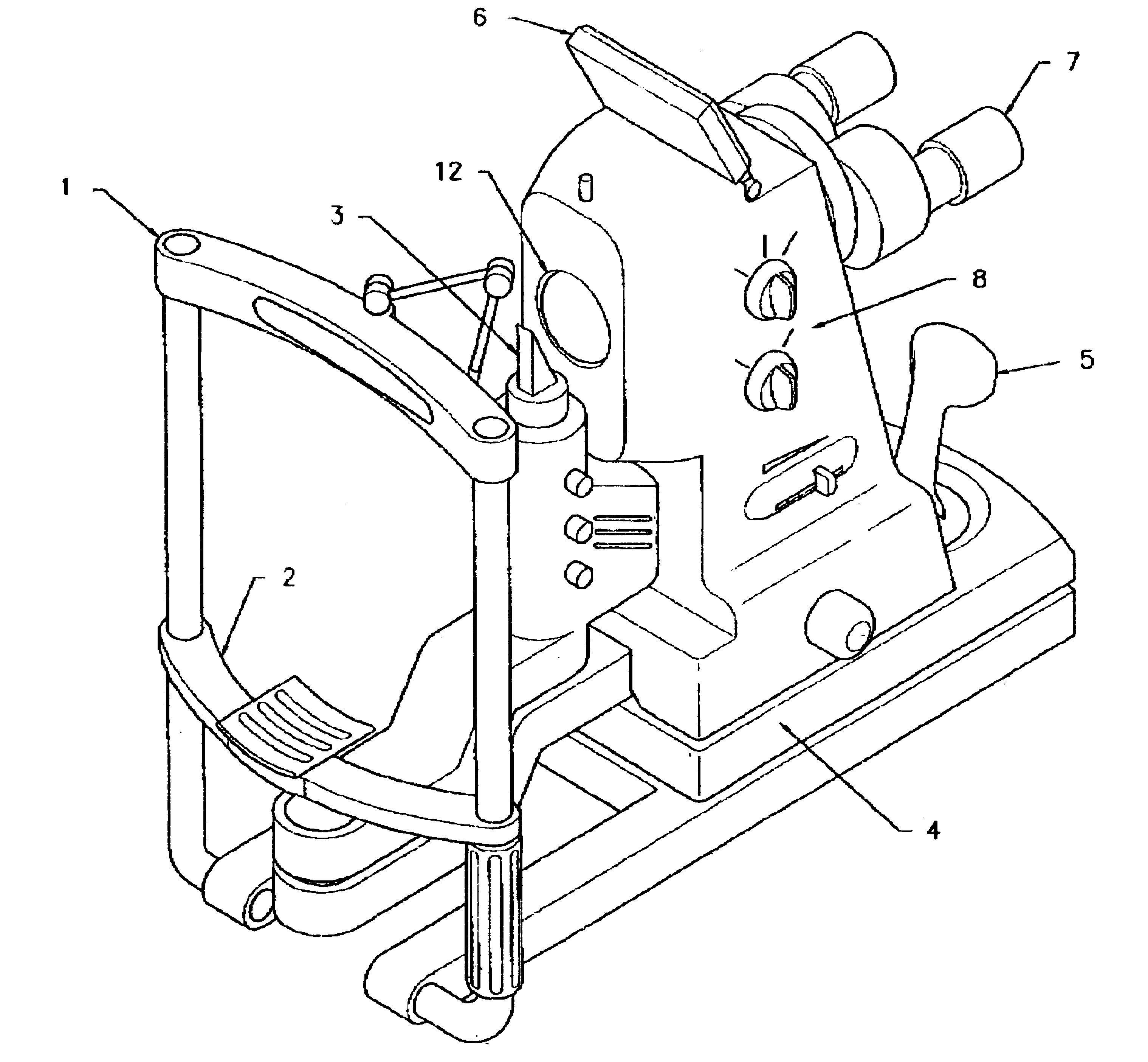
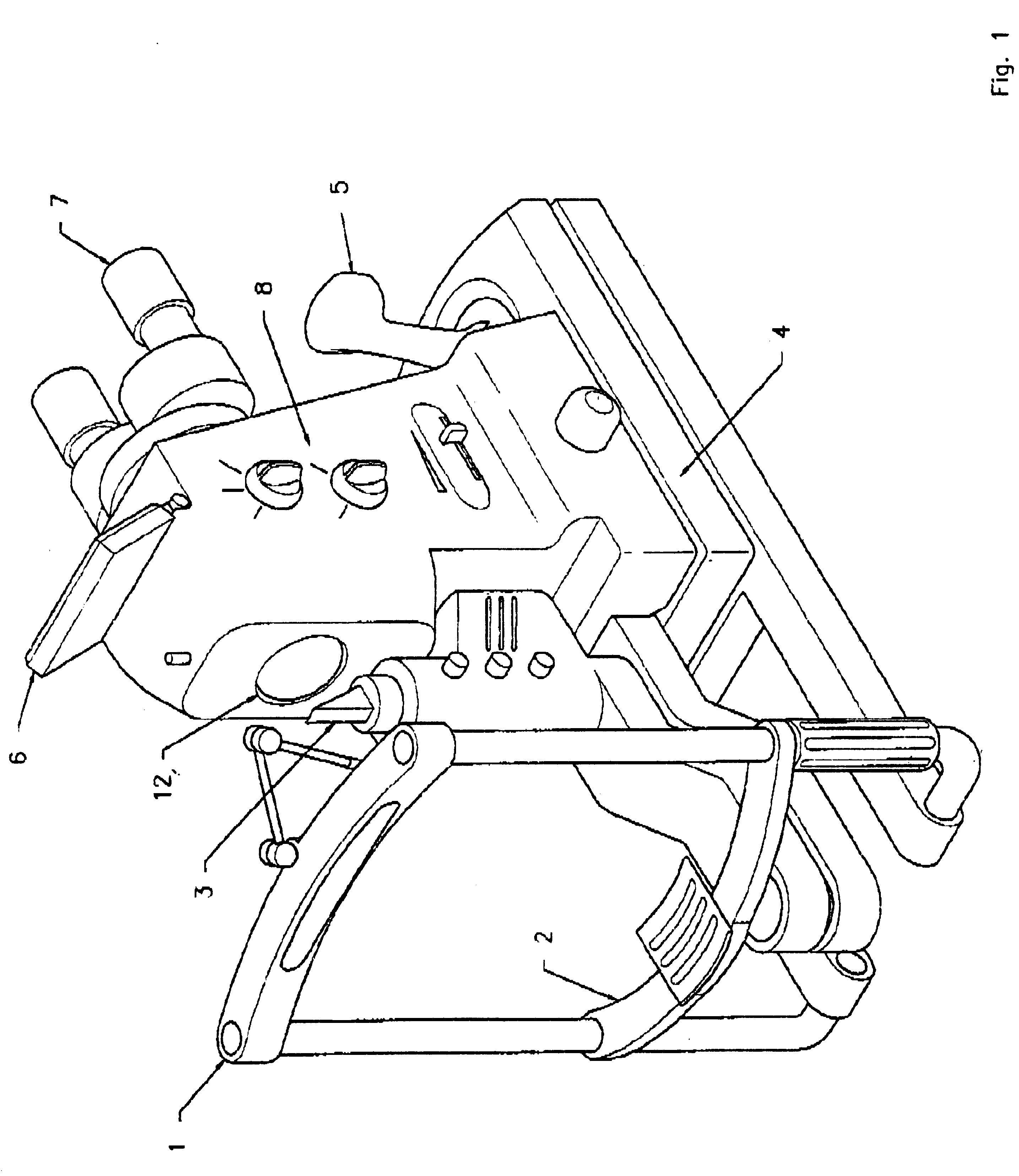
In FIG. 1 is shown the exterior design of a first preferred embodiment of the present invention. A typical headrest 1 and chin rest 2 is provided to stabilize the patient head.

The slit lamp 3 provides illumination for examination of the cornea and is adjustable in brightness, color, and width of slit.

The base 4 provides the usual degrees of freedom in angular, transverse and longitudinal motion. Inside of the camera are means for adjusting the height of the camera potentially through a motorized system. Joystick 5 assists in controlling motion and has control switches for operation of the system. In FIG. 1, the joystick 5 is shown on base 4. Alternatively, the joystick 5 can be mounted on a portable base, and be placed on different position away from the base 4.

A small LCD display 6 can be used to display the image, especially a real-time infrared corneal image. However, the main image display is a larger monitor and is not shown. Oculars 7 are provided for achieving ...


PUM


Abstract

A digital camera that combines the functions of the retinal camera and corneal camera into one, single, small, easy to use instrument. The single camera can acquire digital images of a retinal region of an eye, and digital images of a corneal region of the eye. The camera includes a first combination of optical elements for making said retinal digital images, and a second combination of optical elements for making said corneal digital images. A portion of these elements are shared elements including a first objective element of an objective lens combination, a digital image sensor and at least one eyepiece for viewing either the retina or the cornea. The retinal combination also includes a first changeable element of said objective lens system for focusing, in combination with said first objective element, portions or all of said retinal region at or approximately at a common image plane. The retinal combination also includes a retinal illuminating light source, an aperture within said frame and positioned within said first combination to form an effective retinal aperture located at or approximately at the lens of the eye defining an effective retinal aperture position, an infrared camera for determining eye position, and an aperture adjustment mechanism for adjusting the effective retinal aperture based on position signals from said infrared camera. The cornea combination of elements includes a second changeable element of said objective lens system for focusing, in combination with said first objective element, portions or all of said cornea region at or approximately at a common image plane.

Description

This invention relates to eye cameras and in particular to digital eye cameras.Eye ExaminationsEye health-care practitioners generally divide patient examination into three parts: examination of the cornea, examination of the retina, and a vision function exam including measurement of the refractive status of the eye. The doctor's findings need to be recorded and the standard method for last century has been to make hand-written notes in the chart. Hand recording of vision function and refractive status is completely satisfactory. Vision function is basically a quantitative assessment by the doctor and six numbers describe the refractive information of both eyes so that the manual recording process is quick and efficient. Recording the clinical status of the cornea and retina is completely different.For the retinal and corneal eye-health exams what is needed is quantitative clinical data but what has usually been recorded in the past is the doctor's clinical assessment. For example,...

Claims


Application Information

Patent Timeline
IPC IPC(8): A61B3/14A61B3/135A61B3/13A61B3/117A61B5/00A61B3/10A61B3/107A61B3/12A61B18/18A61F9/01
CPCA61B3/107A61B3/12A61B3/135A61F9/008A61B5/0002A61F2009/00846A61F2009/00863A61F2009/00872A61B3/14
Inventor SU, WEIMASSIE, NORBERT A.
Owner CLARITY MEDICAL SYST
Why Eureka
Try Eureka