Apparatus and method for controlling power generation for hybrid vehicle

a hybrid vehicle and power generation technology, applied in the direction of electric generator control, machines/engines, transportation and packaging, etc., can solve the problems of engine stall, engine fuel consumption increase undesirably, engine stalling, etc., to suppress the generation amount, reduce the load applied to the engine by the motor for power generation, and temporarily reduce the generation amount.

Inactive Publication Date: 2002-03-26
HONDA MOTOR CO LTD
View PDF8 Cites 37 Cited by
  • Summary
  • Abstract
  • Description
  • Claims
  • Application Information

AI Technical Summary

Benefits of technology

According to these aspects, a state of the hybrid vehicle in which a torque load to be applied to an engine of the hybrid vehicle should be decreased is detected, and the generation amount to be generated by a motor is decreased. Therefore, engine stall can be prevented and a smooth start of the vehicle is possible.
According to this apparatus, when the state of the engine is shifted from the idling state to the non-idling state, the generation amount by the motor is temporarily decreased (for example, for 0.5 to 1 second), and the load applied to the engine by the motor for power generation is diminished. Therefore, while the generation amount is suppressed, the load torque applied to the engine can be diminished, and a smooth start of the vehicle is possible.

Problems solved by technology

However, when the engine is idling, should the total torque load of the load for the power generation by the motor, the load generated by a creep state of an automatic transmission system, and the load for activating an air conditioner, etc., be greater than the torque generated by the engine, there arises a problem that the engine will stall.
In particular, when the hybrid vehicle is at high altitudes, this problem occurs more easily because the intake pressure of the engine is lower.
If the idling speed of the engine is increased in order to prevent the engine from stalling, there arises another problem that the fuel consumption of the engine will undesirably increase.
Therefore, the load for driving the motor (that is, power generation torque) is applied to the engine in addition to the torque for driving the vehicle, and the problem arises that smoothness at the time of starting the vehicle will be degraded.

Method used


Image

  • Apparatus and method for controlling power generation for hybrid vehicle
  • Apparatus and method for controlling power generation for hybrid vehicle
  • Apparatus and method for controlling power generation for hybrid vehicle

Examples


first embodiment

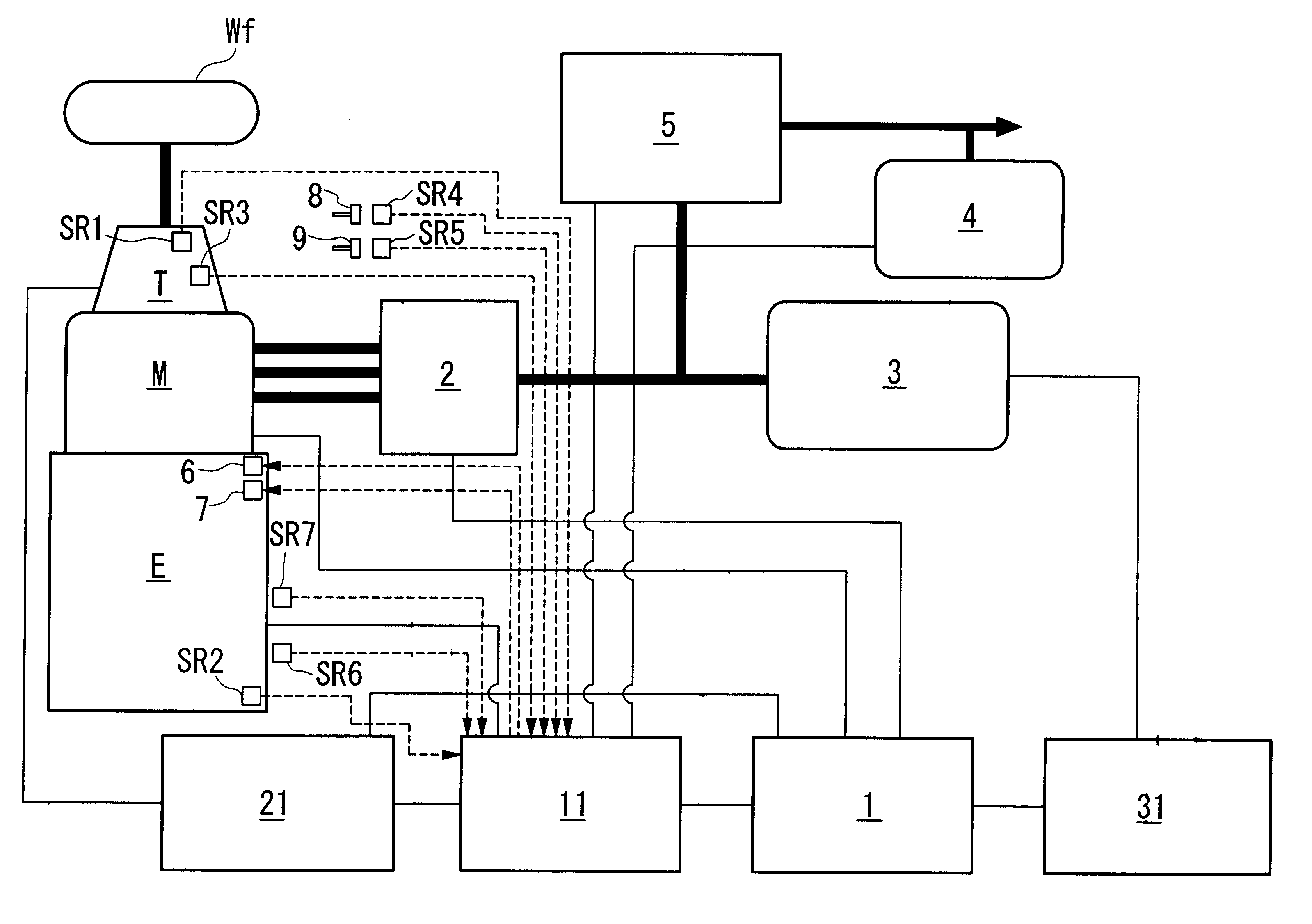
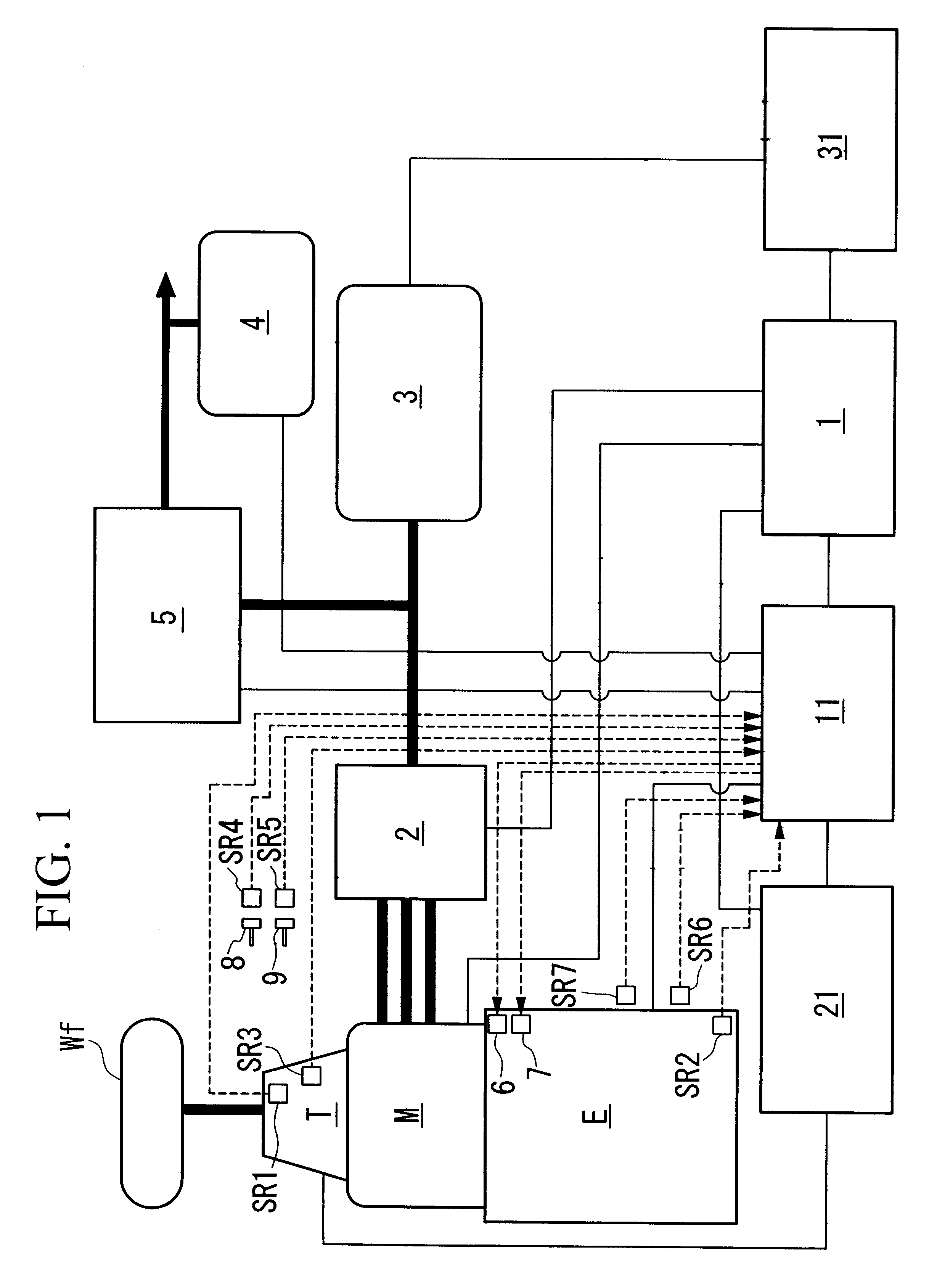
FIG. 1 is a block diagram illustrating a parallel hybrid vehicle in which the present invention is applied, and the vehicle comprises an engine E and an electric motor M. The driving force generated by both the engine E and electric motor M is transmitted via automatic or manual transmission T to the driving wheels Wf. In this embodiment, a CTV (Continuously Variable Transmission) is used as the transmission T. At the time of the deceleration of the hybrid vehicle, the driving force is transmitted from the driving wheels Wf to the electric motor M, the electric motor M functions as a generator for generating what is termed regenerative braking force, that is, the kinetic energy of the vehicle body is recovered as electric energy.

The driving of the motor M and the regenerating operation of the motor M are controlled by a power drive unit 2 according to control commands from a motor ECU 1. A high voltage battery 3 for sending and receiving electric energy to and from the motor M is co...

second embodiment

Hereinafter, the second embodiment of the present invention will be explained referring to FIGS. 6 to 9. FIG. 6 is a block diagram illustrating a parallel hybrid vehicle in which the second embodiment of the present invention is applied. In FIG. 6, elements which are substantially identical to those in FIG. 1 are denoted by the same referential symbols.

The vehicle comprises, as a power source for driving the vehicle, an engine E for generating the driving force for the vehicle, and an electric motor M for assisting the driving force of the engine E. The driving force generated by both the engine E and electric motor M is transmitted via automatic or manual transmission T to the driving wheels Wf.

When the vehicle is idling or cruising, the engine E rotates the electric motor M, and the motor M generates electric power as a power generator to charge the battery 3. When the vehicle decelerates, the driving force is transmitted from the driving wheels Wf to the electric motor M, the ele...


PUM


Abstract

The present invention relates to a power generation control apparatus for a hybrid vehicle. The hybrid vehicle comprises an engine which outputs a driving force for the hybrid vehicle; a motor which outputs an assistant driving force so as to assist the driving force of the engine; a power storage unit; and a power generation control apparatus which controls the power generation by the motor. The power generation control apparatus comprises a load torque calculation device which calculates the load torque to be applied to an engine of the hybrid vehicle for generating electrical power used in the hybrid vehicle when the engine is idling; a generable torque calculation device which calculates torque generable by the engine when the engine is idling; and a power generation load torque determination device which determines a limiting value of a power generation load torque to be applied to the engine in accordance with the load torque calculated by the load torque calculation device and the generable torque calculated by the generable torque calculation device.

Description

1. Field of the InventionThe present invention relates to an apparatus and method for controlling power generation in a hybrid vehicle which comprises an engine and an electric motor as a power source for driving the vehicle. In particular, the present invention relates to a technique for controlling power generation amount when the engine is idling.2. Description of Related ArtConventionally, hybrid vehicles which carry motors as power sources for driving the vehicles in addition to engines are known. Hybrid vehicles are divided into series hybrid vehicles and parallel hybrid vehicles. In the series hybrid vehicles, the engine drives a generator whose electric power output is used to drive the motor, which in turn drives the wheels. In this case, because the output of the engine is not mechanically connected to the driving wheels, the engine can be constantly driven within an engine-speed range of a high fuel mileage and a low emissions level. Therefore, the series hybrid vehicles ...

Claims


Application Information

Patent Timeline
Patent Type & Authority Patents(United States)
IPC IPC(8): B60K6/00B60K6/04B60K6/485B60K6/54B60W10/08B60W10/26B60W20/00
CPCB60K6/485B60K6/54B60W10/08B60W10/26B60L2240/423Y02T10/642B60W2710/065B60W2710/083B60W2710/086Y02T10/6226Y10S903/917B60W20/00B60L50/15Y02T10/62Y02T10/64Y02T10/7072B60W2050/0012B60W30/18027B60W20/10
Inventor IZUMIURA, ATSUSHIKIYOMIYA, TAKASHIOKI, HIDEYUKINAKAUNE, KANKURODA, SHIGETAKAMATSUBARA, ATSUSHIKITAJIMA, SHINICHITAKAHASHI, HIDEYUKI
Owner HONDA MOTOR CO LTD
Why Eureka
Try Eureka