System and method for reducing the rendering load for high depth complexity scenes on a computer graphics display

a computer graphics and scene technology, applied in the field of computer graphics displays, can solve the problems of increasing scene complexity of computer-generated imagery, high dependence, and the number of pixels that must be computed, and achieve the effect of reducing the pixel rendering load and cost-effectiveness

Inactive Publication Date: 2002-03-26
ROCKWELL COLLINS SIMULATION & TRAINING SOLUTIONS
View PDF8 Cites 62 Cited by
  • Summary
  • Abstract
  • Description
  • Claims
  • Application Information

AI Technical Summary

Benefits of technology

An object of this invention is to provide cost-effective, enhanced methods to reduce th

Problems solved by technology

One area that has been accelerating rapidly is computer-generated imagery with increasing scene complexity.
However, the number of pixels that must be computed in order to fill the frame buffer is highly dependent on the complexity of the virtual scene.
If the viewer's position is moved down within the trees, with a line of sight toward the horizon, the depth complexity numbers will increase dramatically.
As the model complexity increases the depth complexity numbers will also increase.
Many pixels rendered in high depth complexity scenes never contribute to the final image.
The additional unused calculations increase the amount of hardware or time required to render a given scene.
As the virtual enviromnent's complexity increases, the demand on the rendering process also increases.
If the rendering is done in accelerated graphics hardware, it can become quite costly because of the large number of calculations required to be implemented in hardware.
For software based rendering systems, the rendering time can become very slow.
In either case, if the rendering is too slow, the movement of the display image becomes disjointed or choppy when the image is displayed.
Computing the pixel color can be very complex if sophisticated lighting algorithms and textures are being used.
A major disadvantage of the

Method used


Image

  • System and method for reducing the rendering load for high depth complexity scenes on a computer graphics display
  • System and method for reducing the rendering load for high depth complexity scenes on a computer graphics display
  • System and method for reducing the rendering load for high depth complexity scenes on a computer graphics display

Examples


Embodiment Construction

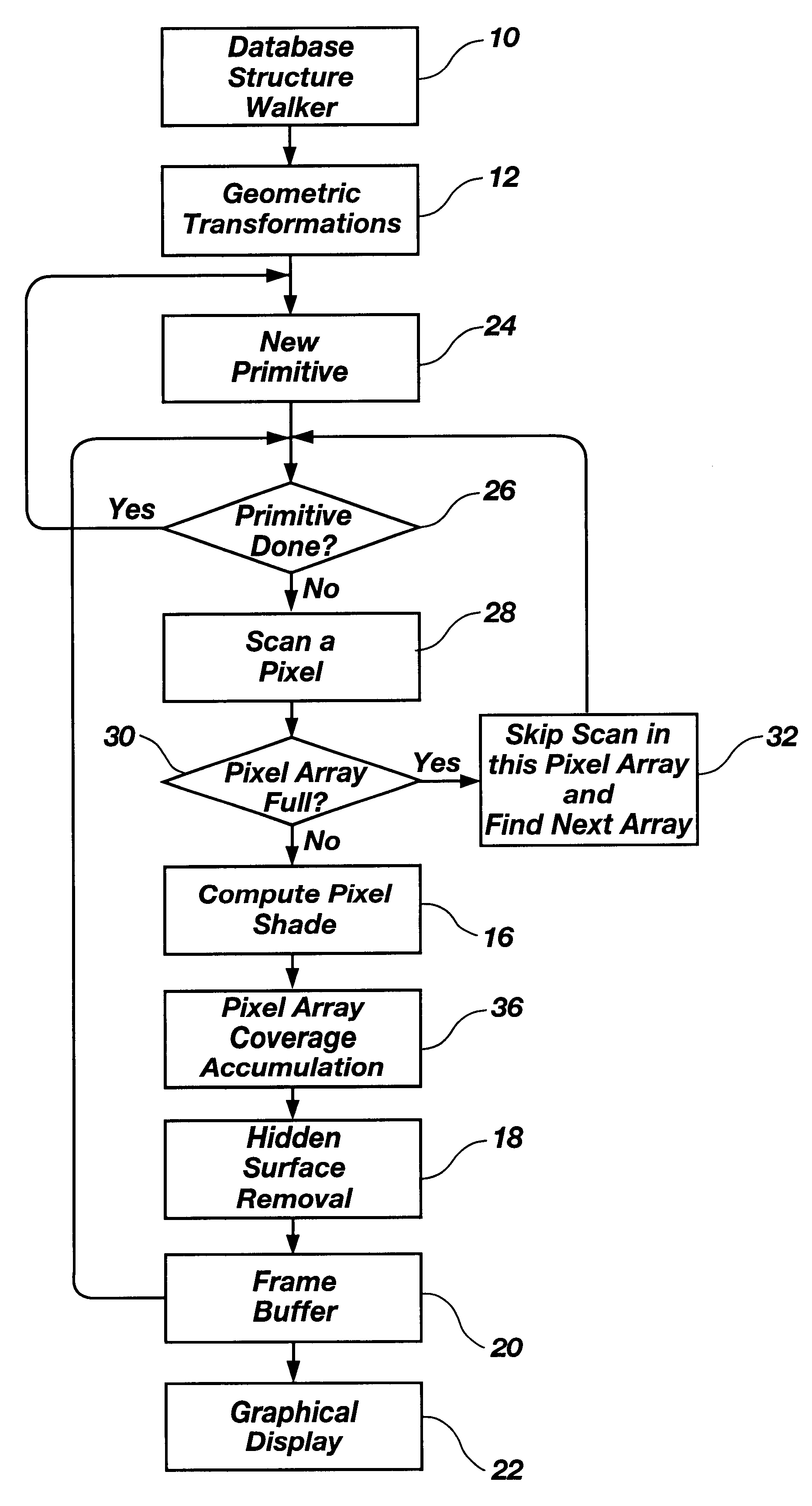
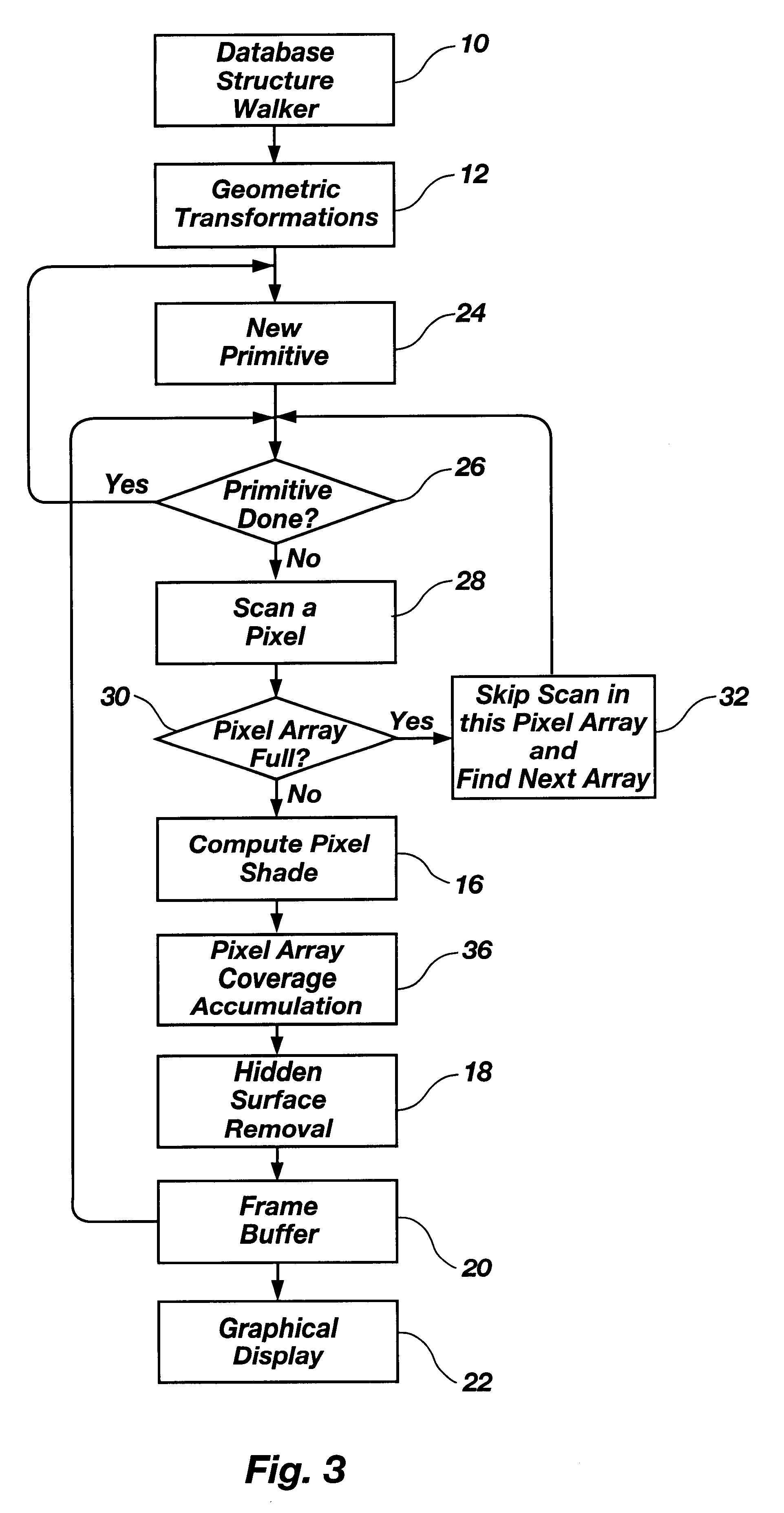
Reference will now be made to the drawings in which the various elements of the present invention will be given numerical designations and in which the invention will be discussed in greater detail so as to enable one skilled in the art to make and use the invention.

Simplified Full Buffer.

Referring first to FIG. 3, a simplified full buffer embodiment of the present invention is shown. FIG. 3 is a flow diagram describing the data flow during the process. At step 10 a database structure is evaluated. The geometric transformations are carried out at step 12.

Once the fill buffer has been initialized, the pixel rendering process can begin. Steps 24, 26, 28, 30 and 32 together determine which pixels need processing for a given primitive. As each pixel array of the primitive is identified, it is tested against the full buffer at step 30 to see if it can be skipped. The speed improvement comes from (1) skipping the shading (at step 16) and z-buffer calculations (at step 18) for pixels which...


PUM


Abstract

This invention relates generally to the field of computer graphics display, and more particularly to reducing the amount of time needed to render complex virtual scenes on a computer graphics display. This invention combines the advantages of the prior art methods of list priority and depth buffering (e.g. Z-buffering) with new simplified and enhanced full buffer processes. In one embodiment, a simplified full buffer arrangement enables the elimination of rendering primitives prior to pixel shading for regions of the screen which have previously been covered by closer primitives. Another embodiment provides for an enhanced full buffer that combines the coverage of a previously rendered primitive in a partial buffer and associates it with a current primitive to cover pixel arrays. This enhanced full buffer technique enables the use of higher order model primitives such as strips, fans and meshes, to increase the effectiveness of the full buffer by allowing more than one primitive to combine to fill a scanned pixel region on the screen.

Description

TECHNICAL FIELDThis invention relates generally to the field of computer graphics display, and more particularly to reducing the amount of time needed to render complex virtual scenes on a computer graphics display.Computers have been used for many years to do image and graphics generation. In recent years these computer-generated graphics have become more and more sophisticated. As the power of computer equipment increases, the users' expectation of what the computer should do also increases. One area that has been accelerating rapidly is computer-generated imagery with increasing scene complexity. Computer users have come to expect more realism that generally means that there are more objects and more lighting and texture processing on those objects.Complex images and scenes are modeled in three-dimensional space in the computer memory and manipulated accordingly. A complex three-dimensional shape is broken down into basic graphic shapes called primitives. Modeling techniques and ...

Claims


Application Information

Patent Timeline
IPC IPC(8): G06T15/10G06T15/40
CPCG06T15/40
Inventor GARDINER, HAROLD D.URRY, RUSSELL J.
Owner ROCKWELL COLLINS SIMULATION & TRAINING SOLUTIONS
Why Eureka
Try Eureka