
Method and apparatus for a virtual system time clock for digital audio/video processor

a virtual system and audio/video processor technology, applied in the field of digital audio and video data processing, can solve the problems that the stc from the demultiplexer cannot be readily used in the video decoding process to satisfy all of the interactive requirements of the current playback system, and the nature of current entertainment equipment presents additional problems, so as to improve the processing of audio and video data, smooth and seamless playback, and minimal distortion

Inactive Publication Date: 2002-03-26
SONY CORP +1
View PDF7 Cites 61 Cited by
  • Summary
  • Abstract
  • Description
  • Claims
  • Application Information

AI Technical Summary

Benefits of technology

The present invention provides a method and apparatus for improving the processing of audio and video data in response to a user selecting trick play modes of operation. The invention permits the seamless concatenation of discontinuous audio and video streams. The present invention has an advantage of providing a smooth and seamless play back with minimal distortion of both audio and video data in which both of the audio and video data have a transition that moves backward in time.

Problems solved by technology

The implementation of digital signal processing for providing a video display and associated audio from an audio-video source of programmed material presents numerous design challenges that were not encountered in the prior processing of analog audio and video signals.
The interactive nature of current entertainment equipment presents additional problems in a synchronized playback of audio, video and subpicture data.
Therefore, the STC from the demultiplexer cannot be readily used by the video decoding process to satisfy all of the interactive requirements of current playback systems.

Method used


Image

  • Method and apparatus for a virtual system time clock for digital audio/video processor
  • Method and apparatus for a virtual system time clock for digital audio/video processor
  • Method and apparatus for a virtual system time clock for digital audio/video processor

Examples


Embodiment Construction

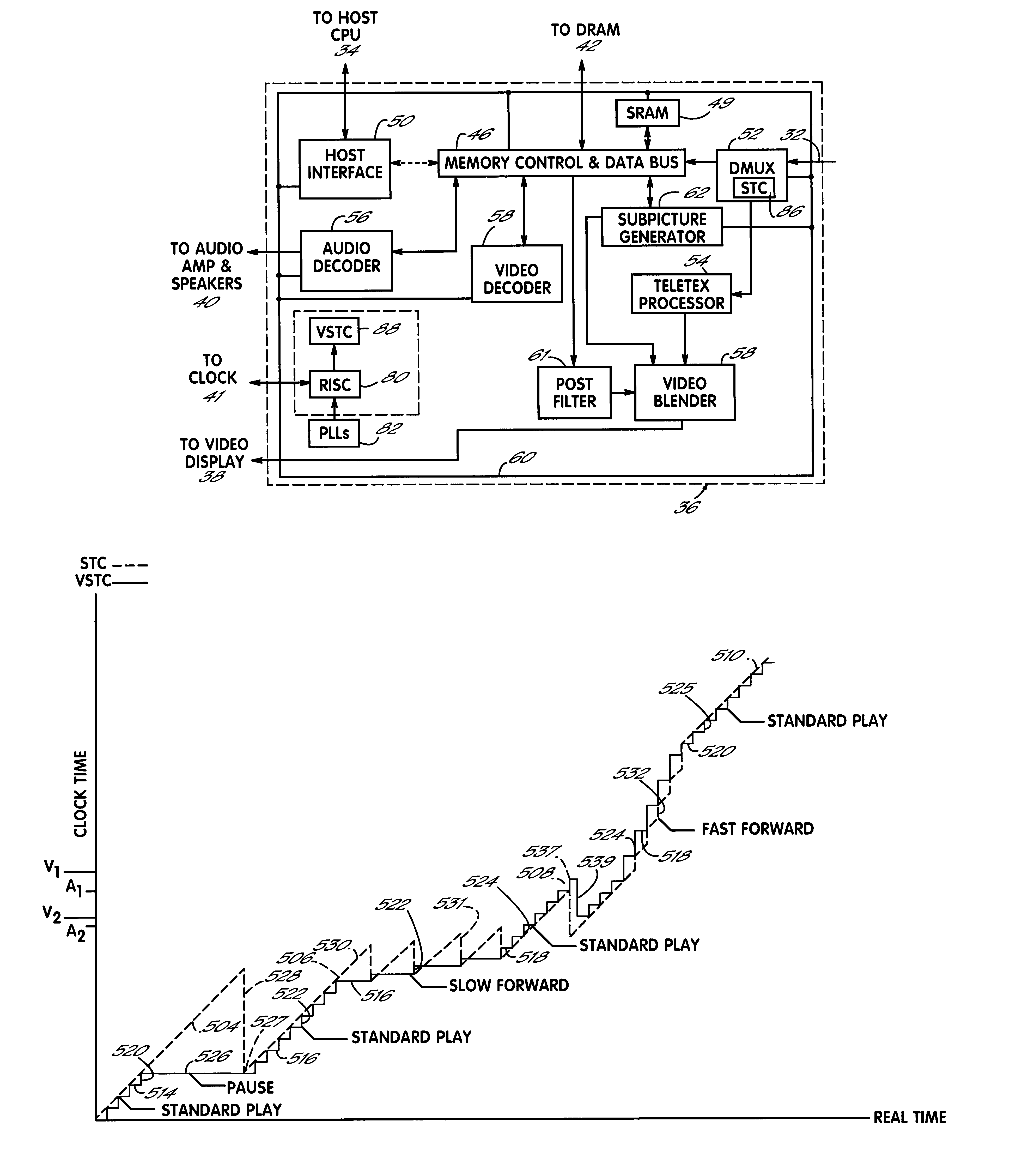
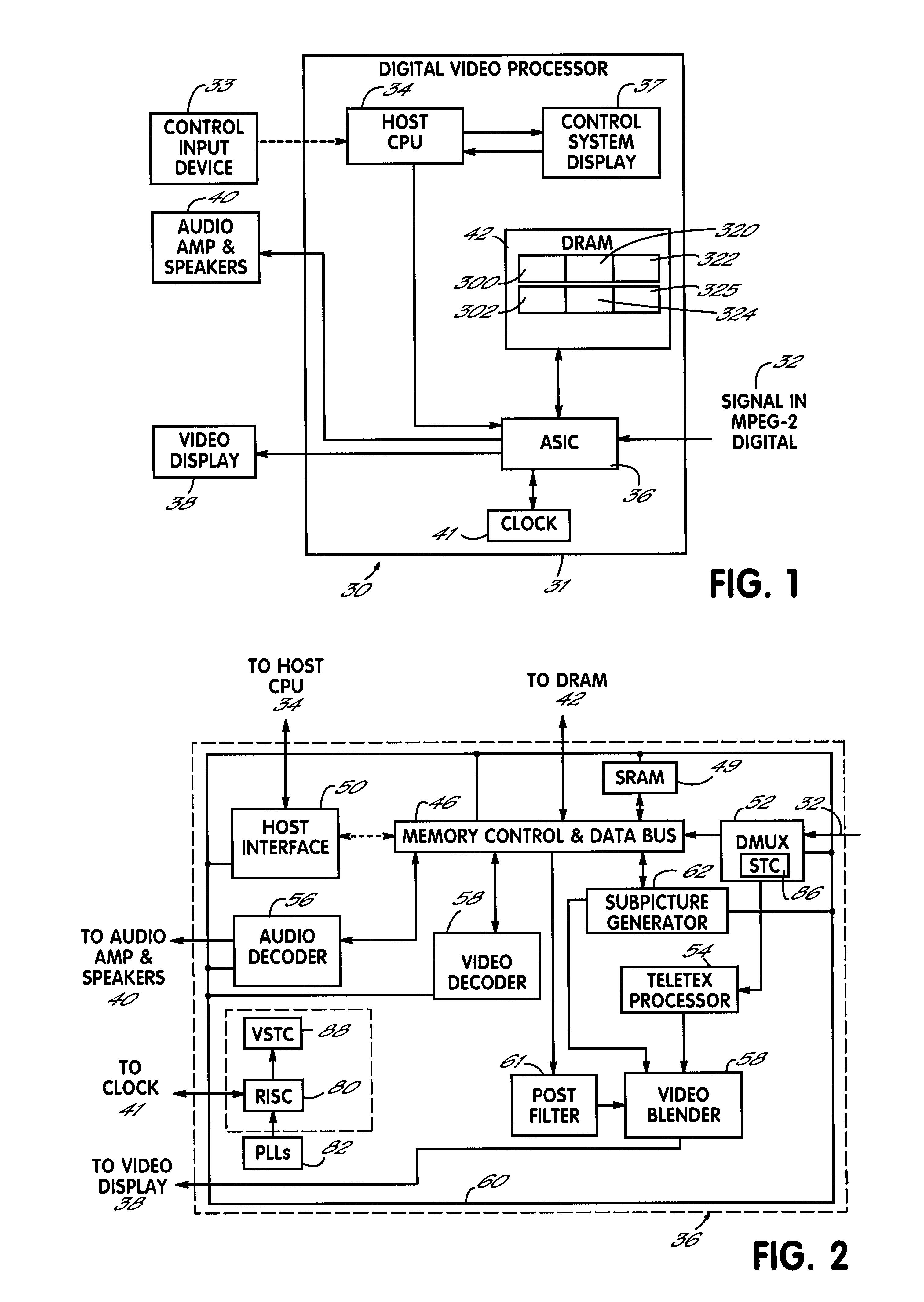
One embodiment of the present invention is for use in a DVD digital audio / video processor. FIG. 1 diagrammatically represents a digital audio / video processor 30 receiving and audio and video presentation system, which includes a unit processor 31 with a program signal input 32 in the form of an antenna, a cable, DVD, CD ROM or other medium through which an MPEG-2 digital input signal is received. A central processing unit or host CPU 34 which is programmed to process user commands from a control input device (not shown) operates a control system display which displays information, menu selections and other information to the user and which may or may not also function as an input device. An Application Specific Integrated Circuit ("ASIC") 36, when provided with configuration and selection information by the host CPU 34, decodes the raw signal from signal input 32 for output to the video and audio presentation devices 38 and 40, respectively. A local system clock 41 preferably is con...


PUM


Abstract

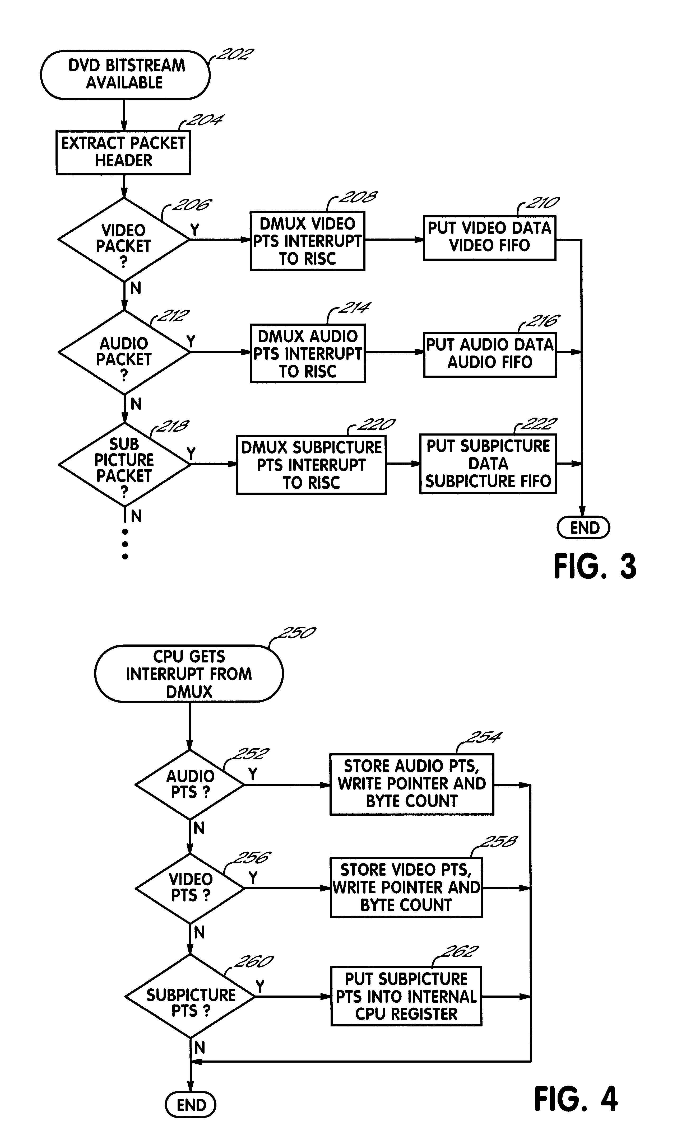
A digital video processor and operating method for a receiving raw audio and video data representing images and sound to be played. The processor includes a demultiplexer for receiving the raw audio and video data and providing demultiplexed audio and video data to a memory. A first system time clock provides first time values in response to being continuously clocked by the demultiplexer. A CPU decodes and plays back the audio and video data as a function of the audio and video PTS values. The processor further includes a second system time clock providing second time values in response to being periodically incremented by the CPU. The CPU periodically sets the second system time clock to a second time value equal to a current first time value of the first system time clock in response to a standard play mode, and the CPU periodically sets the first system time clock to a first time value equal to a current second time value of the second system time clock in response to a trick play mode.

Description

BACKGROUND OF THE INVENTIONThis invention relates to the processing of digital audio and video data to be played through a television and more particularly, to the processing of audio and video data during nonstandard playback modes.Almost all televisions manufactured today are capable of interfacing with different sources of program materials, for example, a VCR, a digital versatile disk ("DVD") player, cable, DSS, etc., that provide audio signals for creating sounds and associated video input signals for creating screen displays. Some of those sources provide digital audio and video input signals in accordance with the Moving Picture Expert Group MPEG-2 audio / video digital compression standard. Further, most televisions and / or their plug compatible program sources have user interactive capabilities with which a user may choose to have the programmed source provide a subpicture display of captions, subtitles, karaoke or simple animation on the screen along with the program material...

Claims


Application Information

Patent Timeline
IPC IPC(8): H04N7/62H04N9/804H04N7/52H04N5/04H04N5/60H04N5/44H04N5/45H04N9/806H04N9/82H04N5/783H04N21/43H04N21/434H04N21/439H04N21/44H04N21/472
CPCH04N5/04H04N5/4401H04N5/45H04N5/602H04N9/8042H04N21/47217H04N21/4307H04N21/4341H04N21/4392H04N21/44004H04N5/783H04N9/8227H04N9/8063H04N21/426H04N21/43072
Inventor DURUOZ, CEMOZCELIK, TANERYU, GONG-SAN
Owner SONY CORP
Learn More