Visual programming method and its system

Inactive Publication Date: 2002-04-02
MITSUBISHI ELECTRIC CORP
View PDF15 Cites 342 Cited by
  • Summary
  • Abstract
  • Description
  • Claims
  • Application Information

AI Technical Summary

Benefits of technology

As a result, the user is capable of doing work to create a more sophisticated program with ease and a high degree of efficiency.
Further, the system adopting the visual programming method according to the present invention comprises a behavioral rule

Problems solved by technology

For the end user, it is as very difficult to master a conventional programming language used for developing a program.
However, there is still a pending issue that the programming problem of sequence processing, the function of each link object, is not solved.
As described above, while the visual programming tool based on the conventional rudder diagram allows a complicated program to be created, there is a problem that it is difficult to use the tool unless the user has the knowledge of a specialist.
Even though such an environment has been proposed for use by the end user of personal computers and workstations, it is still difficult to solve the problem.
Thus, the problem can be converted into a problem caused by the fact that it is necessary to provide a new user interface that allows a program to be creat

Method used


Image

  • Visual programming method and its system
  • Visual programming method and its system
  • Visual programming method and its system

Examples


first embodiment

The operations of the visual programming method provided by the first embodiment and the system adopting the method are explained as follows.

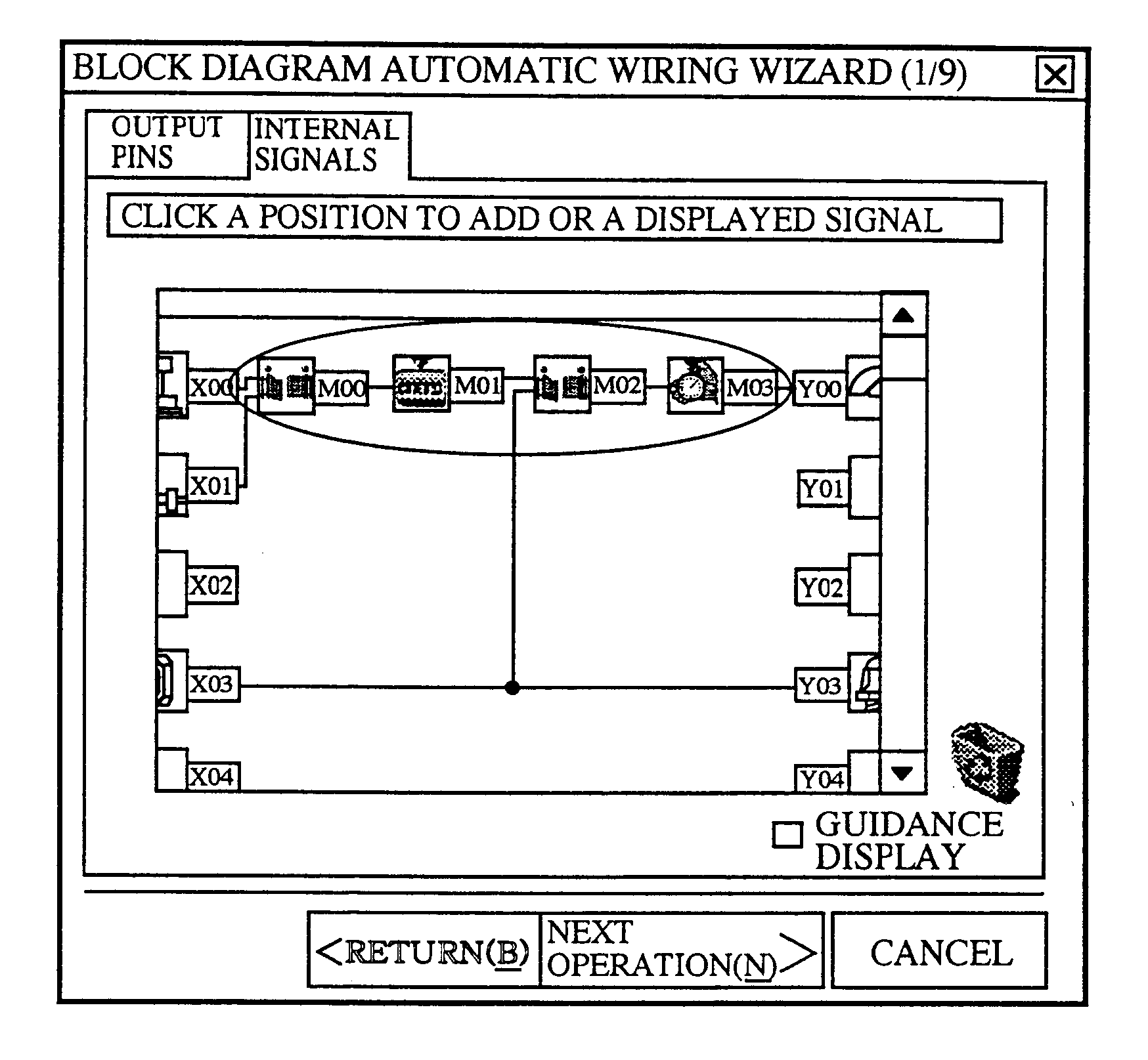
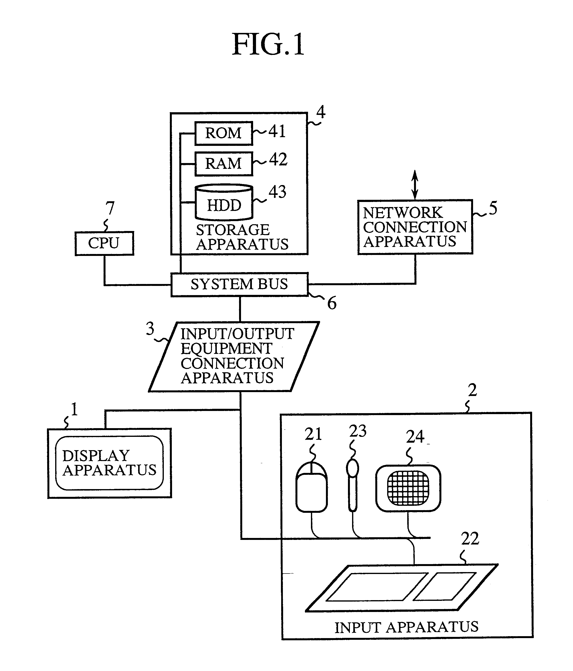
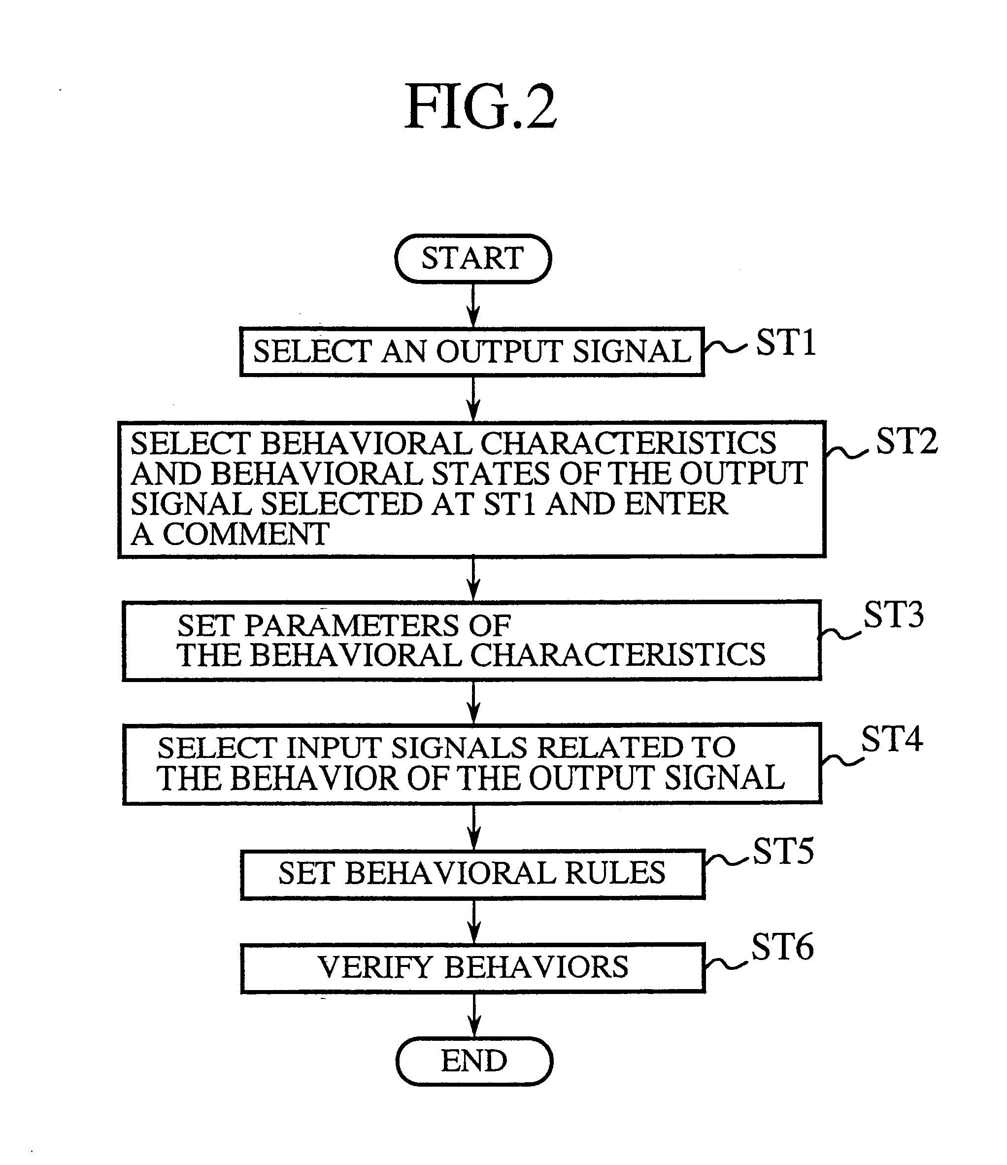
First of all, the object selection means 8 displays the signal box 200 shown in FIG. 3 on the display apparatus 1. Then, the object selection means 8 detects the fact that a graphical object for defining the behavior of a load connected thereto has been selected by the user using typically the mouse 21 of the input unit 2, and stores the name of an output signal represented by the selected graphical object typically in the RAM unit 42 of the storage apparatus 4.

Subsequently, the behavior selection means 9 displays the behavioral characteristic selection window 300 shown in FIG. 4 on the display apparatus 1. The behavior selection means 9 then detects the type of a behavioral characteristic selected from a group of behavioral characteristics 301 and the type of a behavioral state selected from a group of behavioral conditions 302 by the user usi...

second embodiment

FIG. 25 is a block diagram showing a system adopting the visual programming method as implemented by a second embodiment of the present invention. In the figure, reference numerals 12 and 69 denote a behavioral parameter setting means and a behavior selection means respectively. The visual programming system implemented by the second embodiment is a system provided with a user interface which allows a value set for a behavioral characteristic selected by the behavior selection means 69 to be changed. It should be noted that elements of the second embodiment identical with those of the first embodiment are denoted by the same reference numerals as the latter and their explanation is omitted to avoid duplication of description. The visual programming system implemented by the second embodiment is stored typically in the hard disc drive (HDD) 43 shown in FIG. 1 to be executed by the CPU 7 in conjunction with the display apparatus 1, the input apparatus 2 and other components.

The visual...

third embodiment

FIG. 28 is a block diagram showing a system adopting the visual programming method as implemented by a third embodiment of the present invention. As shown in the figure, the visual programming system also includes a behavioral rule generation means 13a, a generated rule display means 13b, a system generated rule modification means 13c and a behavioral rule addition means 13d. The behavioral rule generation means 13a, the system generated rule display means 13b, the system generated rule modification means 13c and the behavioral rule addition means 13d each constitute a user interface. It should be noted that, since the object selection means 8, the behavior selection means 69, the relevant object selection means 10 and the behavioral parameter setting means 12 are identical with those of the second embodiment, they are denoted by the same reference numerals as the latter and their description is omitted to avoid duplication of explanation. The visual programming system implemented b...


PUM


Abstract

The user is allowed to automatically generate a program by using a visual programming method and a system adopting the method for automatically generating a program wherein an object selection means 8 is used for selecting a behavioral graphical object defining the behavior of a load connected thereto, a behavior selection means 9 is used for selecting the type of the behavior of the behavioral graphical object, a relevant object selection means 10 is used for selecting relevant graphical objects related to the behavior of the behavioral graphical object and a behavioral rule setting means 11 is used for setting behavioral rules of the behavioral graphical object whereas a behavioral characteristic selection unit 3509 is used for selecting a behavior of a behavioral graphical object selected by using a behavioral object selection unit 3508, behavioral condition setting unit 3510 is used for setting conditions for the behavior of the behavioral graphical object and a relevant object selection unit 3511 is used for defining a relation.

Description

In general, the present invention relates to a visual programming method and a system adopting the method. More particularly, the present invention relates to a visual programming method, that is, a user interface technique capable of automatically generating a program by selecting an object defining a behavior, defining the behavior and setting behavioral rules by means of a graphical editor. It also relates to a system adopting the method. Technical fields of the present invention include function block diagrams and visual programming tools based on a diagram widely used as a programming language of a programmable logic controller (PLC), and a work environment for carrying out programming by operating graphical objects such as characters and icons which are displayed on a screen and used in a graphical user interface (GUI) commonly known as a user interface between the user and a personal computer or a workstation serving as a graphical editor.With popularization of personal compu...

Claims


Application Information

Patent Timeline
IPC IPC(8): G06F9/44
CPCG05B19/056G06F8/34Y10S715/967G05B2219/13144
Inventor OHARA, EIJISUZUKI, MIDORIKONDO, SHOZOSUETSUGU, NOBUHIROHAGINO, AKIO
Owner MITSUBISHI ELECTRIC CORP
Why Eureka
Try Eureka