Profile corrected label with RFID transponder and method for making same

a technology of rfid transponder and label, applied in the field of labels, can solve the problems of uneven profile physical support and unsupported areas of the label face sheet, and the label's smart label containing an rfid transponder, so as to reduce deformation and bending, and high density and stiffness

Inactive Publication Date: 2002-04-09
INTERMEC IP
View PDF8 Cites 57 Cited by
  • Summary
  • Abstract
  • Description
  • Claims
  • Application Information

AI Technical Summary

Benefits of technology

It is a further object of the invention to present a label having a face sheet with a relatively high density and stiffness to reduce deformation and bending in the face sheet so as to not conform unevenly to the shape of the RFID transponder.

Problems solved by technology

In the past, smart labels containing an RFID transponder presented many problems relating to printing on the label.
The generally uneven profile of an RFID transponder, when inserted into a label by positioning the RFID within layers of the label, results in physically supported areas and unsupported areas of the face sheet of the label.
The face sheet is, as a result, uneven in its profile.
Previously, the use of standard paper and film materials in the construction of a smart label resulted in a non-uniform surface profile for printing.
Because of this uneven profile, when attempting to print on the label utilizing a direct thermal process or a thermal transfer process, uneven images are created on the printable surface.
This circumstance can create critical problems on printed labels, in particular on bar code labels where the bar code image must be uniform enough to be scanned by an optical scanner.
This creates problems in printing, because in order to avoid the RFID transponder, the printer would have to avoid the transponder during the printing process, which involves identifying the exact location of the transponder prior to printing, and then controlling the printer to print around the transponder.
Another problem in prior labels is that in some applications, such as when security is a concern, it is necessary to mask the presence of an RFID transponder in a label.
Prior art materials used in the construction of smart labels did not effectively mask the existence of an RFID transponder in the label.
This defeats the goal of maintaining the security or the anti-counterfeiting capacity of the label.

Method used


Image

  • Profile corrected label with RFID transponder and method for making same
  • Profile corrected label with RFID transponder and method for making same
  • Profile corrected label with RFID transponder and method for making same

Examples


Embodiment Construction

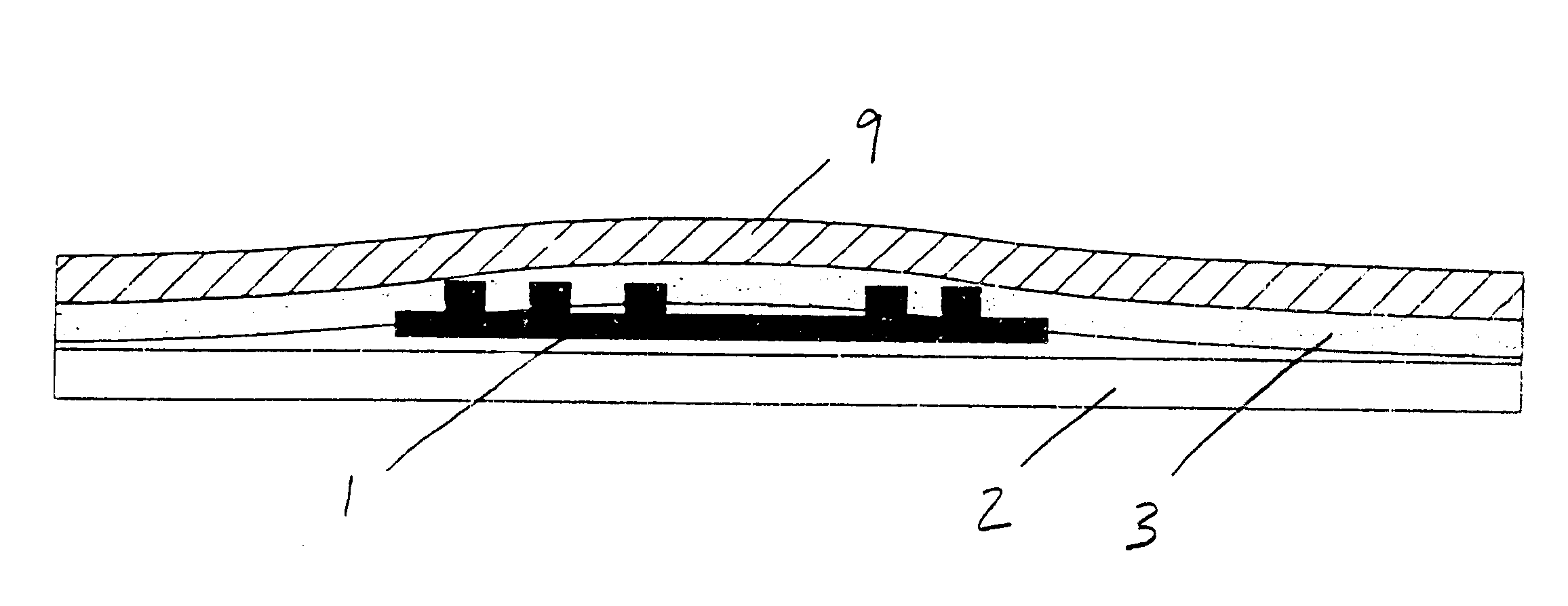
As shown on a prior art FIG. 1, past smart labels containing RFID transponders presented an uneven profile for printing on a face sheet. As seen, the presence of the RFID transponder creates distinct supported and unsupported areas of the face sheet, which in turn results in a surface poorly suited for receiving a uniform image created by a thermal printer.

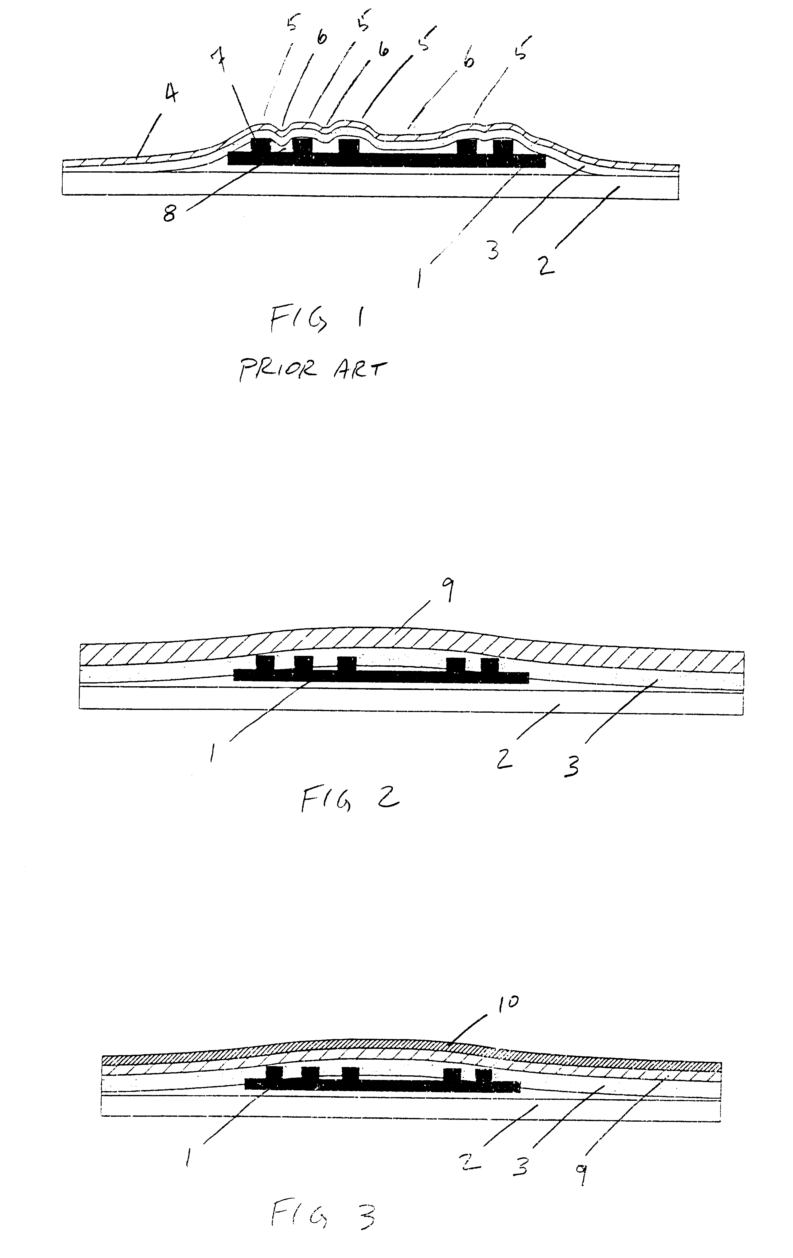
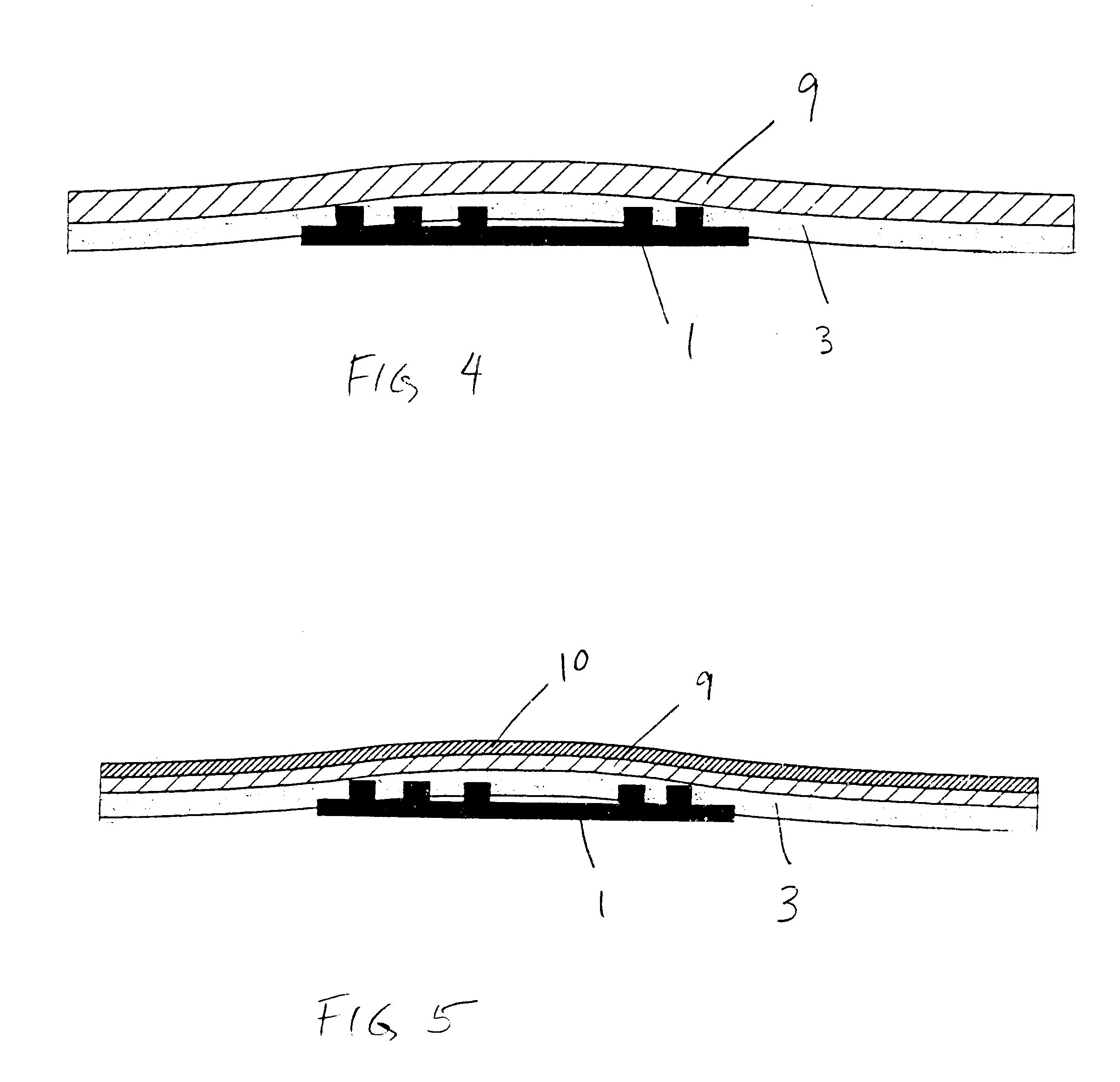
FIG. 2 illustrates a smart label according to the present invention. An RFID transponder 1 is positioned between a liner layer 2 on one side of the RFID transponder 1 an adhesive layer 3 and face sheet 9 on the opposite side of the RFID transponder 1, and from the liner layer 2. The adhesive layer 3 may in one embodiment be thicker in dimension from the prior art adhesive layers. In particular, the first face sheet 9 has a significantly increased thickness and / or rigidity as compared to prior art face sheets. The present invention may also utilize a bending beam construction in one embodiment which results in decreased pressure di...


PUM


Abstract

The present invention sets out a label containing an RFID transponder having a uniform printable surface. The present invention presents a face sheet having an increased rigidity and/or thickness which does not readily conform to the profile of an RFID transponder contained beneath the face sheet. This results in a label having a more readily printable surface, and also presents a label having higher security as a result of the masking of the profile of the contained RFID responder.

Description

1. Field of the InventionThe present invention pertains to labels, such as pressure sensitive labels, which contain an RFID transponder as part of the label. In particular, the invention pertains to printable labels which may be attached to an item using pressure sensitive adhesives. Images may be printed on the labels using thermal printers which rely on heat and / or pressure to create the image, such as direct thermal or thermal transfer printers. The label containing an RFID transponder may be known as a smart label.2. Description of the Related ArtIn the past, smart labels containing an RFID transponder presented many problems relating to printing on the label. The generally uneven profile of an RFID transponder, when inserted into a label by positioning the RFID within layers of the label, results in physically supported areas and unsupported areas of the face sheet of the label. The face sheet is, as a result, uneven in its profile. Previously, the use of standard paper and fil...

Claims


Application Information

Patent Timeline
Patent Type & Authority Patents(United States)
IPC IPC(8): G08B13/24G06K19/077
CPCG06K19/07749G06K19/0776G08B13/2417G08B15/001G08B13/2437G08B13/244G08B13/2434
Inventor ADAMS, MATTHEW T.CONWELL, KEVIN GIRARD
Owner INTERMEC IP
Why Eureka
Try Eureka