Frequency-domain scalable coding without upsampling filters

a frequency domain and filter technology, applied in the field of scalable audio coders, can solve the problems of low calculating expenditure and fast operation

Inactive Publication Date: 2002-04-09
FRAUNHOFER GESELLSCHAFT ZUR FOERDERUNG DER ANGEWANDTEN FORSCHUNG EV
View PDF8 Cites 37 Cited by
  • Summary
  • Abstract
  • Description
  • Claims
  • Application Information

AI Technical Summary

Benefits of technology

An advantage of the present invention consists in that, with the apparatus for coding according to the invention (scalable audio coder), which comprises at least two separate coders, a second coder can operate in optimum marnner in consideration of the psychoacoustic model.
The invention is based on the realization that the upsampling filter involving much calculating time can be dispensed with when an audio coder or decoder, respectively, is employed which performs coding or decoding in the spectral range, and when the formation of the difference and, respectively, the formation of the inverse difference between the coded / decoded output signal of the coder or decoder of lower order and the original input signal, or the spectral representation of a signal based thereon, is carried out with a high sampling frequency in the frequency domain. It is thus no longer necessary to upsample the coded / decoded output signal of the coder of lower order by means of a conventional upsampling filter, but there are only two banks of filters necessary, namely one filter bank for just the coded / decoded output signal of the coder or lower order, and one filter bank for the original input signal with high sampling frequency.

Problems solved by technology

These known coders, such as e.g. the coders G.729, G.723, FS1016 and CELP known to experts, serve mainly for coding speech signals and in general are not suitable for coding higher-quality music signals since they are usually designed for signals sampled with 8 kHz, so that they can code only an audio bandwidth of 4 kHz at maximum.
However, in general they exhibit faster operation and low calculating expenditure.
However, due to the downsampling filter, the signal then obtained contains only useful information with a bandwidth of e.g. 4 kHz.

Method used


Image

  • Frequency-domain scalable coding without upsampling filters
  • Frequency-domain scalable coding without upsampling filters
  • Frequency-domain scalable coding without upsampling filters

Examples


Embodiment Construction

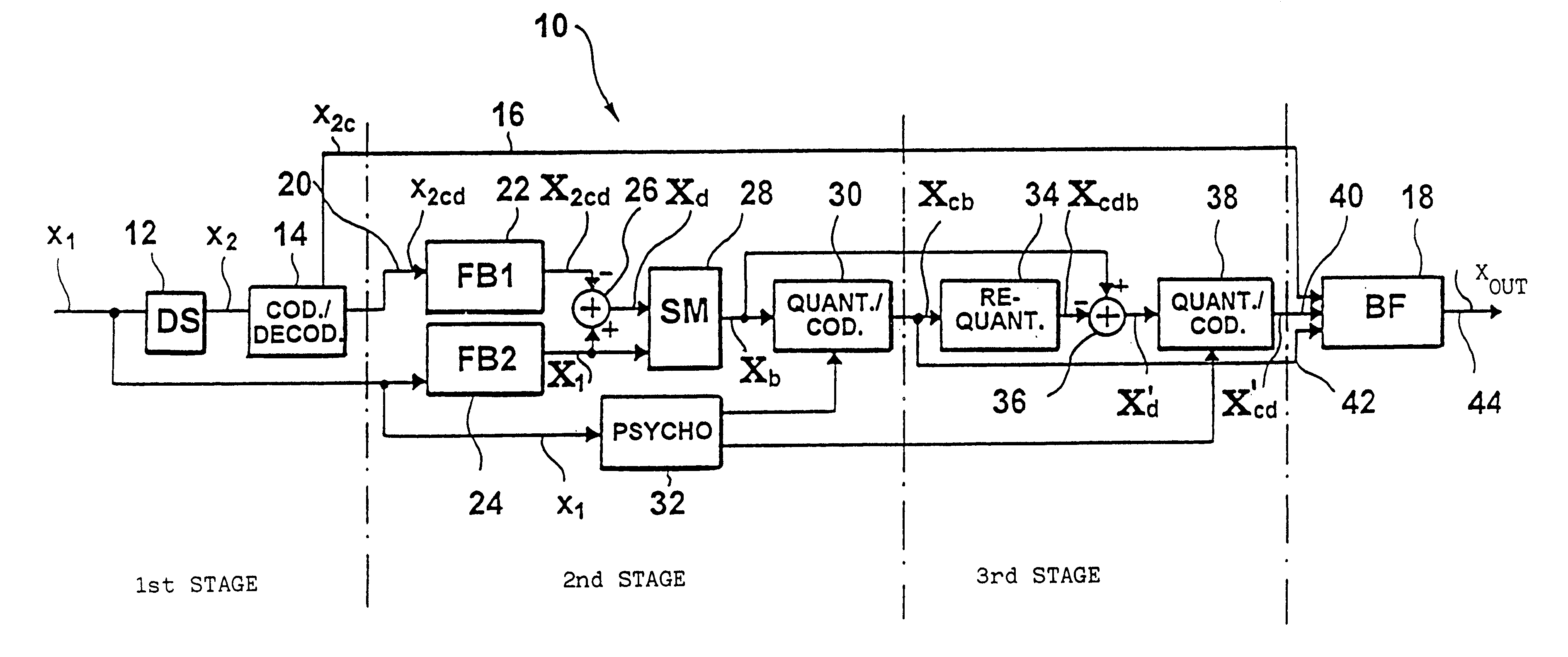
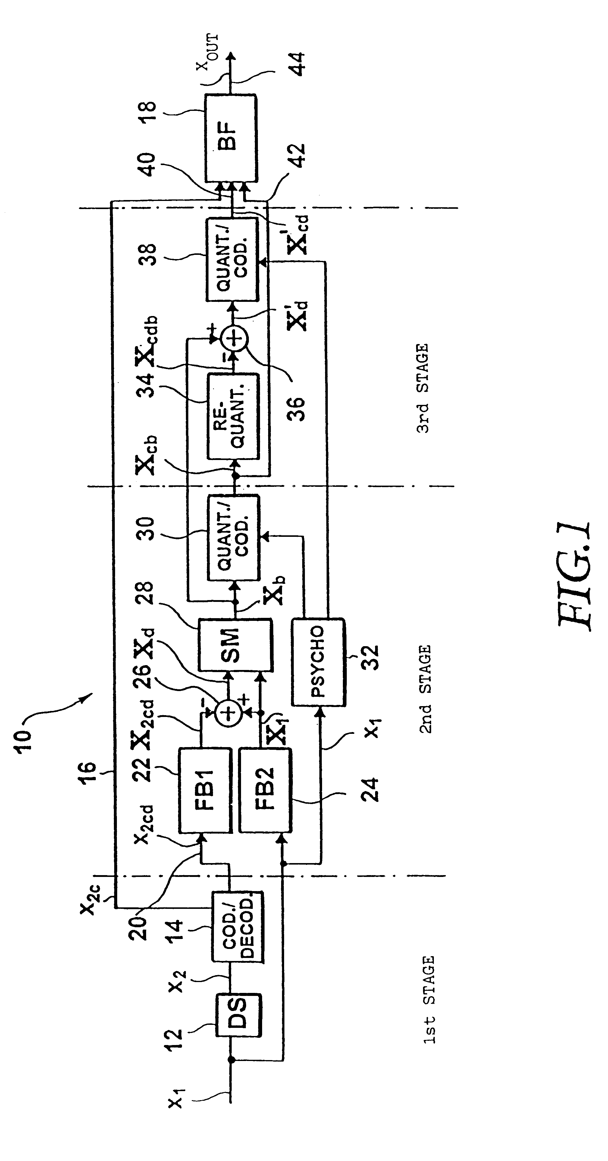
FIG. 1 shows a principle block diagram of an apparatus for coding a time-discrete signal (of a scalable audio coder) according to the present invention. A discrete time signal x.sub.1, sampled with a first sampling rate, e.g. 48 kHz, is brought to a second sampling rate, e.g. 8 kHz, by means of a downsampling filter 12, with the second sampling rate being lower than the first sampling rate. The first and second sampling rates preferably constitute a ratio of an integer. The output signal of the downsampling filter 12, which may be implemented as an decimation filter, is input to a coder / decoder 14 coding its input signal in accordance with a first coding algorithm. As was already mentioned, the coder / decoder 14 may be a speech coder of lower order, such as e.g. a coder G.729, G.723, FS1016, MPEG-4, CELP etc. Such coders operate with data rates from 4.8 kilobit per second (FS1016) to data rates of 8 kilobit per second (G.729). All of them process signals that have been sampled at a s...


PUM


Abstract

In a method of coding discrete time signals (X1) sampled with a first sampling rate, second time signals (x2) are generated using the first time signals having a bandwidth corresponding to a second sampling rate, with the second sampling rate being lower than the first sampling rate. The second time signals are coded in accordance with a first coding algorithm. The coded second signals (X2c) are decoded again in order to obtain coded / decoded second time signals (X2cd) having a bandwidth corresponding to the second sampling frequency. The first time signals, by frequency domain transformation, become first spectral values (X1). Second spectral values (X2cd) are generated from the coded / decoded second time signals, the second spectral values being a representation of the coded / decoded time signals in the frequency domain. To obtain weighted spectral values, the first spectral values are weighted by means of the second spectral values, with the first and second spectral values having the same frequency and time resolution. The weighted spectral values (Xb) are coded in accordance with a second coding algorithm in consideration of a psychoacoustic model and written into a bit stream. Weighting the first spectral values and the second spectral values comprises the subtraction of the second spectral values from the first spectral values in to obtain differential spectral values.

Description

The present invention relates to methods of and apparatus for coding discrete signals and decoding coded discrete signals, respectively, and in particular to implementing differential coding for scalable audio coders in efficient manner.BACKGROUND ART AND DESCRIPTION OF PRIOR ARTScalable audio coders are coders of modular construction. There are endeavors to employ existing speech coders capable of processing signals, which are sampled e.g. with 8 kHz, and of outputting data rates of, for example, 4.8 to 8 kilobit per second. These known coders, such as e.g. the coders G.729, G.723, FS1016 and CELP known to experts, serve mainly for coding speech signals and in general are not suitable for coding higher-quality music signals since they are usually designed for signals sampled with 8 kHz, so that they can code only an audio bandwidth of 4 kHz at maximum. However, in general they exhibit faster operation and low calculating expenditure.For audio coding of music signals, in order to ob...

Claims


Application Information

Patent Timeline
Patent Type & Authority Patents(United States)
IPC IPC(8): G10L19/00G10L19/02H04B14/04H03M7/02G10LG10L19/24
CPCG10L19/24G10L19/0204H03M5/00
Inventor GRILL, BERNHARDEDLER, BERNDBRANDENBURG, KARLHEINZ
Owner FRAUNHOFER GESELLSCHAFT ZUR FOERDERUNG DER ANGEWANDTEN FORSCHUNG EV
Why Eureka
Try Eureka