
System and method for performing accurate demodulation of turbo-encoded signals via pilot assisted coherent demodulation

a technology of coherent demodulation and turbo-encoded signals, applied in the field of communication systems, can solve the problems of increasing the power of transmitted signals, increasing interference to other mobile devices, and being impractical in many applications

Inactive Publication Date: 2002-04-23
QUALCOMM INC
View PDF2 Cites 108 Cited by
  • Summary
  • Abstract
  • Description
  • Claims
  • Application Information

AI Technical Summary

Problems solved by technology

To increase the SIR, the power of the transmitted signal is often increased, which is costly, increases the interference to other mobiles, and, thus, is impractical in many applications.
If redundancy is not employed in a noisy environment, error-free performance is difficult or impossible to obtain.
Co-channel interference occurs when a CDMA communications system maintains multiple system users, with each additional user contributing incrementally to the co-channel interference.
As the velocity of a mobile unit increases, fade duration decreases, leading to shorter error bursts.
As the velocity of the mobile unit decreases, fade duration increases, leading to longer error bursts.
Accurate LLR values are particularly important in turbo decoding applications where the LLR inputs are typically subjected to non-linear operations that can amplify inaccuracies in the LLR values and result in unacceptable decoder performance.
Existing methods for calculating the LLR fail to properly account for uncertainty in the estimate of the channel coefficient, which results in sub-optimal detection and decoding.
However, in practice, the channel coefficient is seldom known exactly, and only a channel estimate is available.
However, the channel estimate has an error factor.
The error factor may become unacceptably large when the channel is characterized by rapid or deep fades.
The resulting inaccuracies are particularly problematic for communications systems employing turbo codes, where inaccuracies in the LLR can result in significantly degraded performance.
Unfortunately, these circuits and methods typically fail to account for uncertainty in the estimate of the channel.
The channel is often subjected to deep and rapid Raleigh fading, which can result in erroneous channel estimates and poor decoding performance due sub-optimal log-likelihood ratios based on the channel estimates.
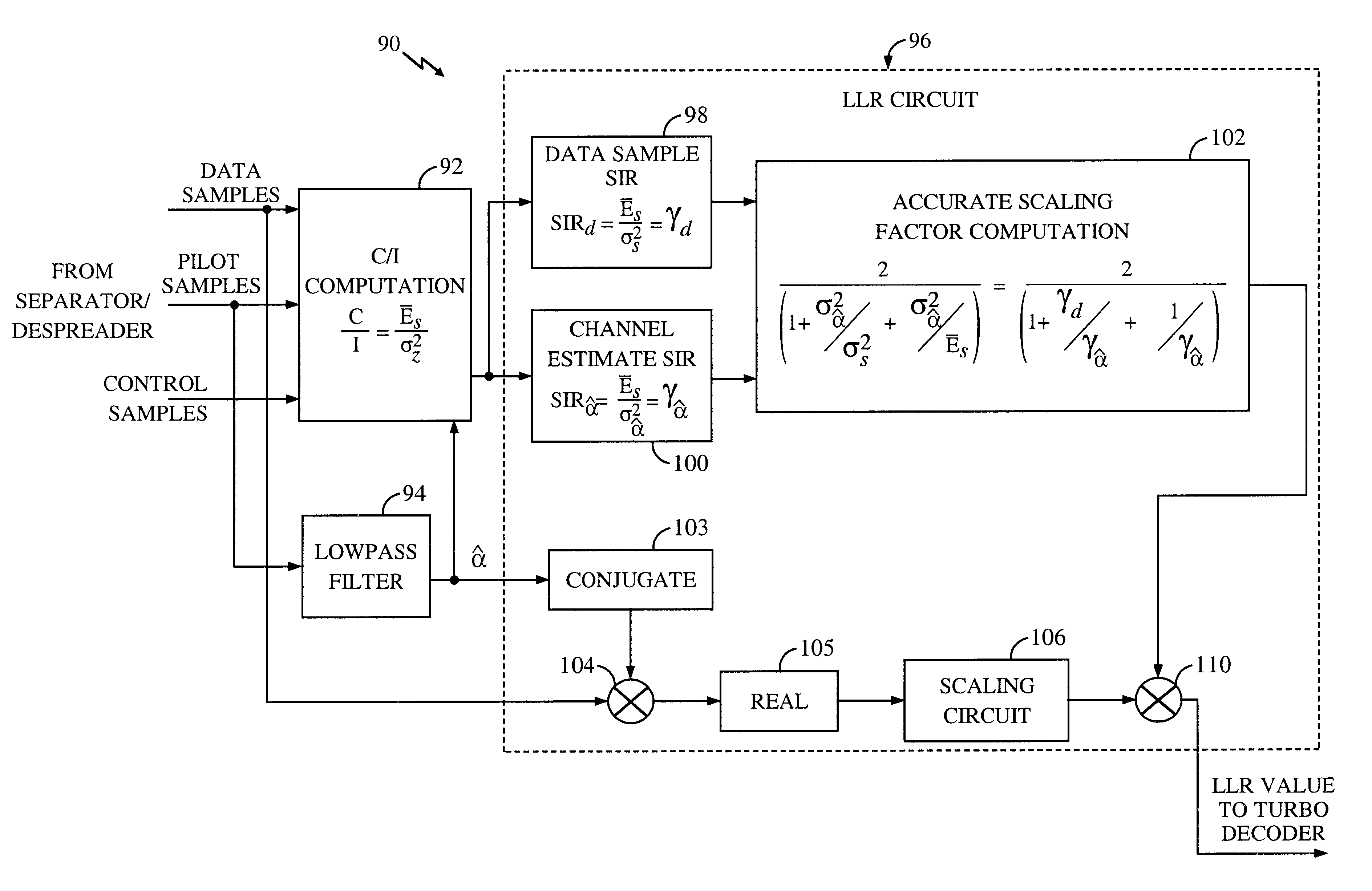
The unique scale factor accounts for inherent error involved in estimating the characteristics of the channel based on the pilot signal.

Method used


Image

  • System and method for performing accurate demodulation of turbo-encoded signals via pilot assisted coherent demodulation
  • System and method for performing accurate demodulation of turbo-encoded signals via pilot assisted coherent demodulation
  • System and method for performing accurate demodulation of turbo-encoded signals via pilot assisted coherent demodulation

Examples


Embodiment Construction

While the present invention is described herein with reference to illustrative embodiments for particular applications, it should be understood that the invention is not limited thereto. Those having ordinary skill in the art and access to the teachings provided herein will recognize additional modifications, applications, and embodiments within the scope thereof and additional fields in which the present invention would be of significant utility.

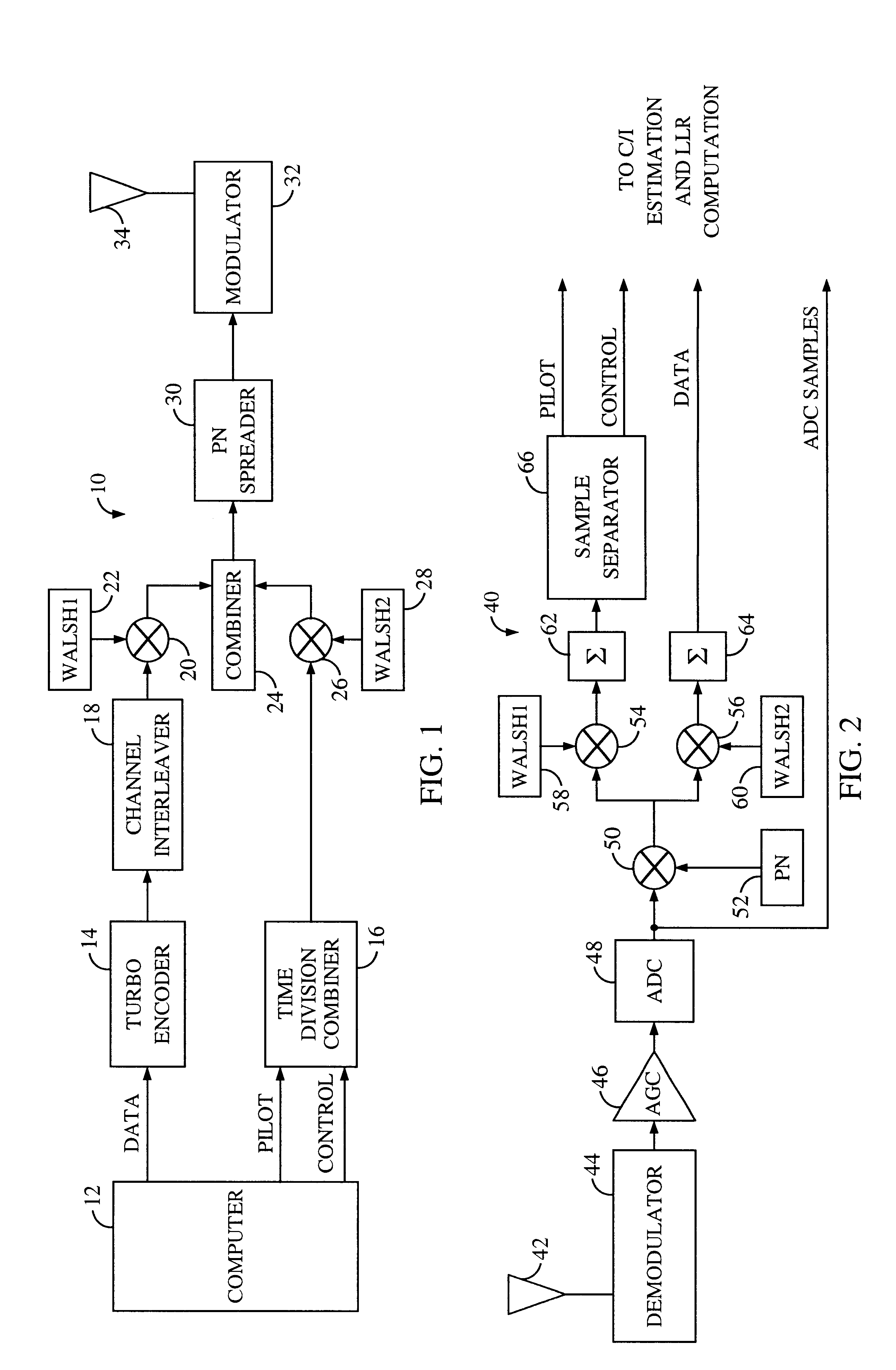
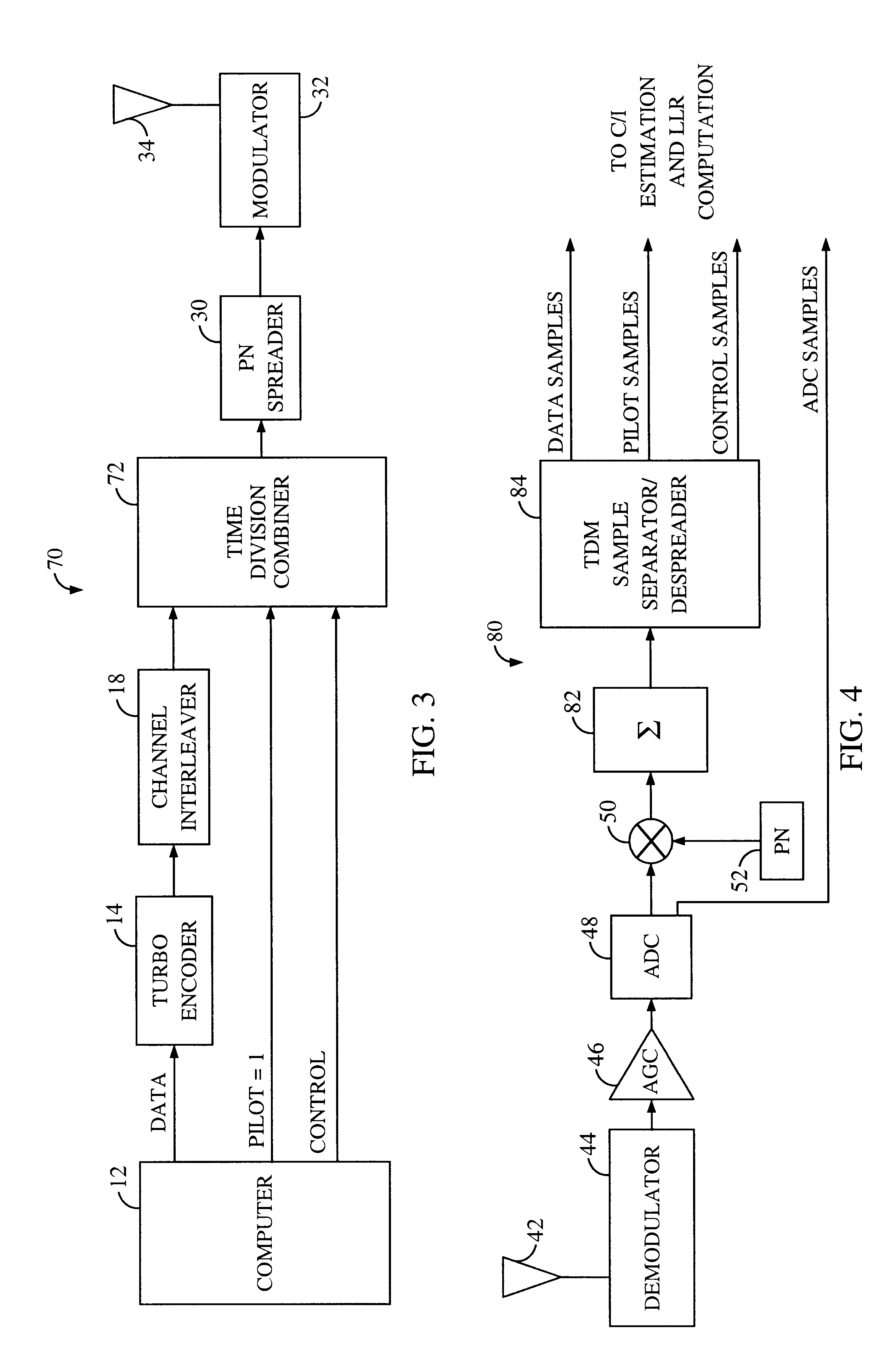
FIG. 1 is a diagram of a code division multiplexing (CDM) transmitter 10 constructed in accordance with the teachings of the present invention. For clarity, various details of the transmitter have been omitted from the drawings such as timing circuitry, filters, and amplifiers. The omitted circuitry is easily constructed an implemented by those having ordinary skill in the art.

The transmitter 10 includes a computer 12 that includes transmitter software executed via a baseband processor (not shown) within the computer 12. The computer 12 is ...


PUM


Abstract

An efficient telecommunications receiver system for accurately decoding a received composite signal having a data signal component and a pilot signal component. The receiver system includes a first circuit for receiving the composite signal and extracting a pilot signal and a data signal from received composite signal. A second circuit calculates a log-likelihood ratio as a function of a channel estimate based on the pilot signal. A third circuit scales the log-likelihood ratio by a predetermined log-likelihood ratio scaling factor and provides an accurate log-likelihood value in response thereto. A fourth circuit decodes the received composite signal based on the accurate log-likelihood value and the data signal. In a specific embodiment, the pilot signal and the data signal comprise pilot samples and data samples, respectively. The third circuit includes a carrier signal-to-interference ratio circuit for computing a first signal-to-interference ratio and a second signal-to-interference ratio based partly on the pilot signal. The first signal-to-interference ratio is based on the data samples, and the second signal-to-interference ratio is based on the pilot samples. The first signal-to-noise ratio and the second signal-to-noise ratio provide input to a circuit for computing the predetermined log-likelihood ratio scaling factor that is included in the third circuit. In a more specific embodiment, the first circuit includes a despreader for despreading the received composite signal in accordance with a predetermined spreading function and providing a despread signal in response thereto. The spreading function is a pseudo noise sequence or a Walsh function. The first circuit further includes a decovering circuit that extracts the pilot signal and the data signal from the despread signal. In the illustrative embodiment, the accurate receiver system further includes a circuit for generating a rate and / or power control message and transmitting the rate and / or power control message to an external transceiver in communication with the efficient receiver system.

Description

1. Field of InventionThis invention relates to communications systems. Specifically, the present invention relates to systems and methods for calculating the log-likelihood ratio to facilitate optimal decoding in receivers employing pilot-assisted coherent demodulation.2. Description of the Related ArtCellular telecommunications systems are characterized by a plurality of mobile transceivers, such as mobile phones, in communication with one or more base stations. Each transceiver includes a transmitter and a receiver.In a typical transceiver, an analog radio frequency (RF) signal is received by an antenna and downconverted by an RF section to an intermediate frequency (IF). Signal processing circuits perform noise filtering and adjust the magnitude of the signal via analog automatic gain control (AGC) circuitry. An IF section then mixes the signal down to baseband and converts the analog signal to a digital signal. The digital signal is then input to a baseband processor for further...

Claims


Application Information

Patent Timeline
IPC IPC(8): H04L1/20H04B1/7097H03M13/23H03M13/25H03M13/29
CPCH03M13/2957H04L1/20H03M13/658H03M13/6337H03M13/23H04B1/7097
Inventor LING, FUYUNSINDHUSHAYANA, NAGABHUSHANA T.ESTEVES, EDUARDO A. S.
Owner QUALCOMM INC
Learn More