X-ray control method and x-ray apparatus

a control method and a technology of x-rays, applied in the direction of diaphragms for radiation diagnostics, medical science, diagnostics, etc., can solve the problems of reducing the amount of light inputted to a television camera, affecting the effect of control, and affecting the efficiency of light utilization

Inactive Publication Date: 2002-04-23
HITACHI MEDICAL CORP
View PDF2 Cites 47 Cited by
  • Summary
  • Abstract
  • Description
  • Claims
  • Application Information

AI Technical Summary

Benefits of technology

An object of the present invention is to provide an X-ray control method and an X-ray apparatus which make it possible to perform the X-ray fluoroscopy / radiography control more pertinently or properly when compared with the conventional techniques in the X-ray fluoroscopy / radiography control in which a video signal is employed.

Problems solved by technology

Consequently, the amount of light inputted to a television camera will decrease, giving rise to a problem that light utilization efficiency is degraded.
Besides, because the light pick-up field is disposed at only one location in the vicinity of the X-ray I.I., difficulty is encountered in effecting the control so that the image having proper or desirable brightness as a whole can be ensured for the X-ray images exhibiting various X-ray absorption dose distributions.
Consequently, in the case where one or more photodiodes are positioned near to a boundary between the X-rays transmitted through an object under inspection and the directly incident X-rays, a slight movement of the object under inspection will bring about significant variation in the amount of X-rays impinging onto these photodiodes, incurring a problem that the tone of the displayed image undergo remarkable variation.
However, this method suffers problems described below and thus encounters difficulty in realization for practical applications.
By way of example, because the dynamic range of the television camera is very narrow when compared with that of the photomultiplier and the photodiode array, halation will take place as the amount of light increases, making it impossible to detect accurately the X-ray output, to a disadvantage.
Furthermore, in the X-ray radiography control, the time taken for controlling the generation of X-rays is short when compared with a time taken for frame reading of the television camera, involving thus another problem.
Additionally, control algorithm for ensuring proper brightness for the fluoroscopic image as well as the radiographic image of a concerned part as required for diagnosis is not definite, bringing about a further problem.

Method used


Image

  • X-ray control method and x-ray apparatus
  • X-ray control method and x-ray apparatus
  • X-ray control method and x-ray apparatus

Examples


Embodiment Construction

In the following, the present invention will be described in detail in conjunction with an exemplary embodiment thereof by reference to the drawings.

By the way, throughout all the views illustrating the exemplary embodiment of the invention, components serving for same function are designated by like reference symbols and repeated description thereof will be omitted.

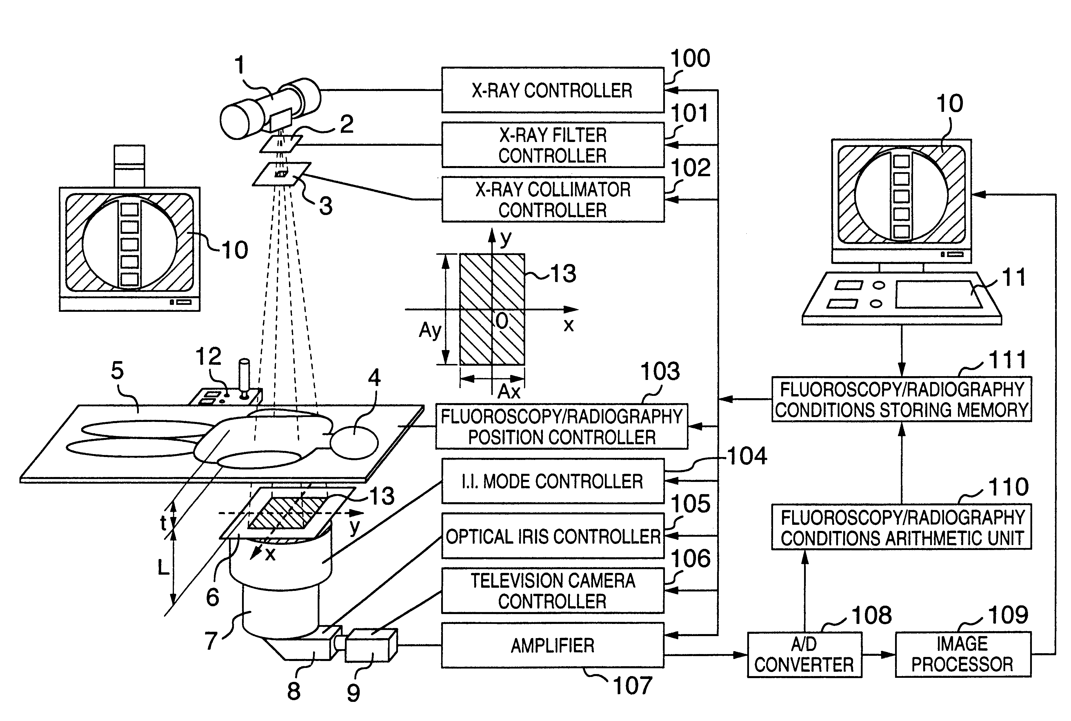
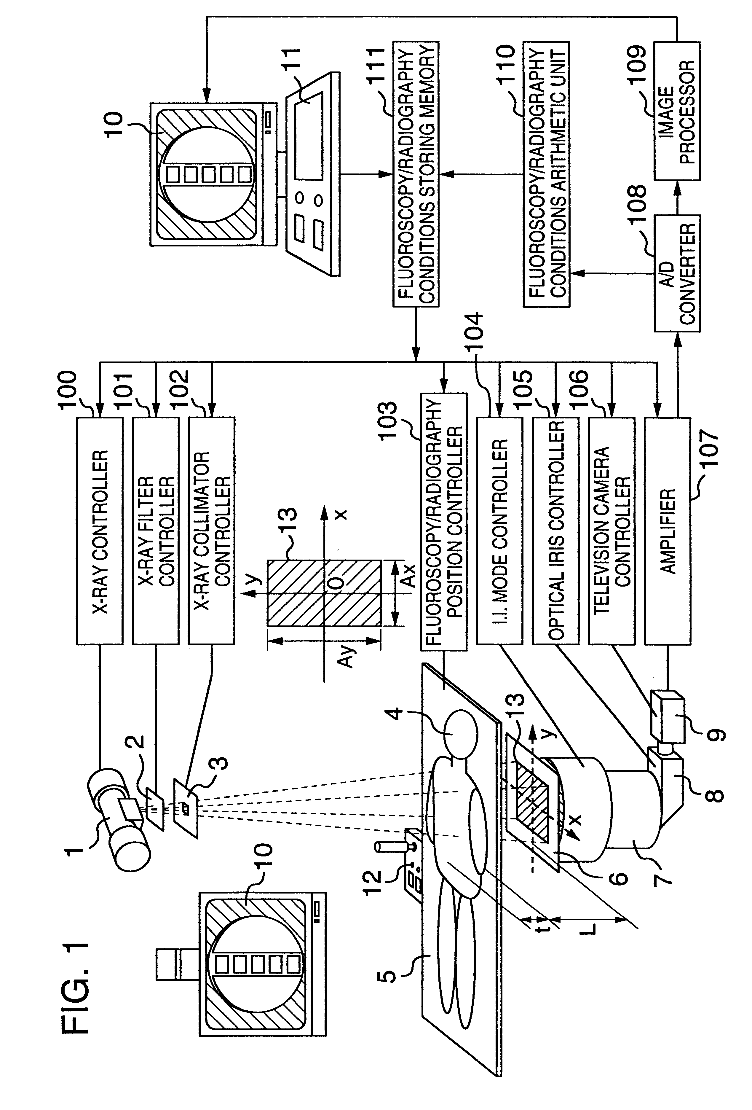
FIG. 1 is a block diagram showing schematically a structure of an X-ray apparatus according to an exemplary embodiment of the present invention. The X-ray apparatus (X-ray fluoroscopy / radiography apparatus) according to the instant embodiment of the invention is comprised of an X-ray tube 1, an X-ray filter 2, an X-ray collimator (X-ray irradiation field limiting means) 3, a bed top board 5, an X-ray grid 6, an X-ray image intensifier (hereinafter referred to as the X-ray I.I.) 7, an optical lens system 8, a television camera 9, a monitor 10, a remote control / manipulation console 11, a control / manipulation console 12, an...


PUM


Abstract

An X-ray apparatus in which a mean value of a weighted histogram obtained by multiplying a histogram of numbers of data corresponding to image intensities in a reference image which is an X-ray image picked up in an X-ray fluoroscopy mode and a weighting function whose variable depends on the image intensities is arithmetically determined for controlling an output power of an X-ray tube so that the mean value of the integrated histogram approaches a predetermined value.

Description

The present invention relates to an X-ray apparatus and more particularly relates to techniques which can effectively be applied to exposure control for controlling properly or pertinently the conditions for generating X-rays in a fluoroscopy as well as in a radiography for X-ray diagnosis.In the conventional X-ray fluoroscopy / radiography system, the automatic X-ray exposure apparatus is so designed as to pick up a portion of output light of an X-ray image intensifier or X-ray I.I. for detection by means of a photomultiplier or the like to thereby effect X-ray fluoroscopy and radiography controls on the basis of the detection signal. By way of example, for the X-ray fluoroscopy control, a feedback control is performed for a tube current and a tube voltage of an X-ray tube or aperture of an optical stop or iris so that an integral value of the detection signal outputted from the photomultiplier per unit time can assume a constant value, whereby brightness of the X-ray fluoroscopic im...

Claims


Application Information

Patent Timeline
Patent Type & Authority Patents(United States)
IPC IPC(8): A61B6/02H05G1/00H05G1/30A61B6/00A61B6/06H05G1/64
CPCA61B6/4225A61B6/469A61B6/548H05G1/30A61B6/488A61B6/06A61B6/583
Inventor UEKI, HIRONORIUEDA, KENKUBA, AKIRA
Owner HITACHI MEDICAL CORP
Why Eureka
Try Eureka