Tire defect detection system and method

a tire defect and detection system technology, applied in the direction of mechanical roughness/irregularity measurement, instruments, ways, etc., can solve the problems of high cost of holography methods, large drawbacks of prior art devices, and inability to map tire defects using optical means,

Inactive Publication Date: 2002-04-30
FOSTER-MILLER
View PDF4 Cites 31 Cited by
  • Summary
  • Abstract
  • Description
  • Claims
  • Application Information

AI Technical Summary

Problems solved by technology

As such, when a retreaded tire fails due to a delamination, the result can be disastrous.
Such prior art devices, however, suffer from numerous drawbacks.
Holography methods, which map tire defects using optical means are extremely expensive, generally about $500,000 per machine, are extremely sensitive to vibration, and also relatively slow.
Shearography is a similar technique less sensitive to vibration, but also very expensive and slow.
High voltage tests are less expensive, but are limited to detecting only metal inclusions in the tire carcass.
Ultrasound techniques are capable only of detecting air-filled defects, are very sensitive to the thickness of

Method used


Image

  • Tire defect detection system and method
  • Tire defect detection system and method
  • Tire defect detection system and method

Examples


Embodiment Construction

Other objects, features and advantages will occur to those skilled in the art from the following description of a preferred embodiment and the accompanying drawings, in which:

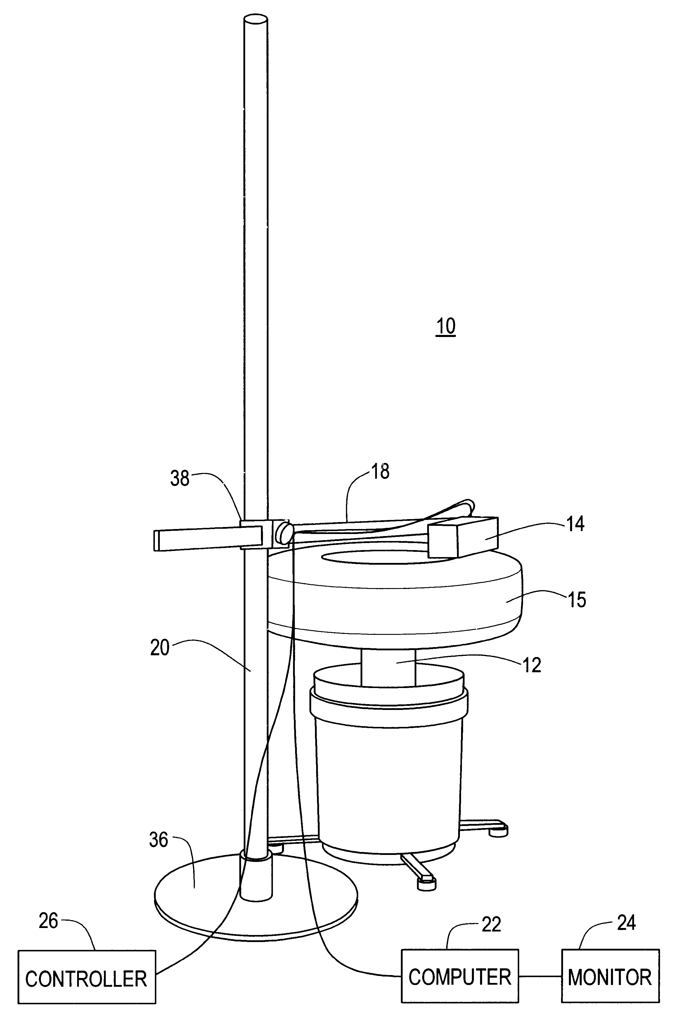
FIG. 1 is a schematic view of the tire defect system of this invention;

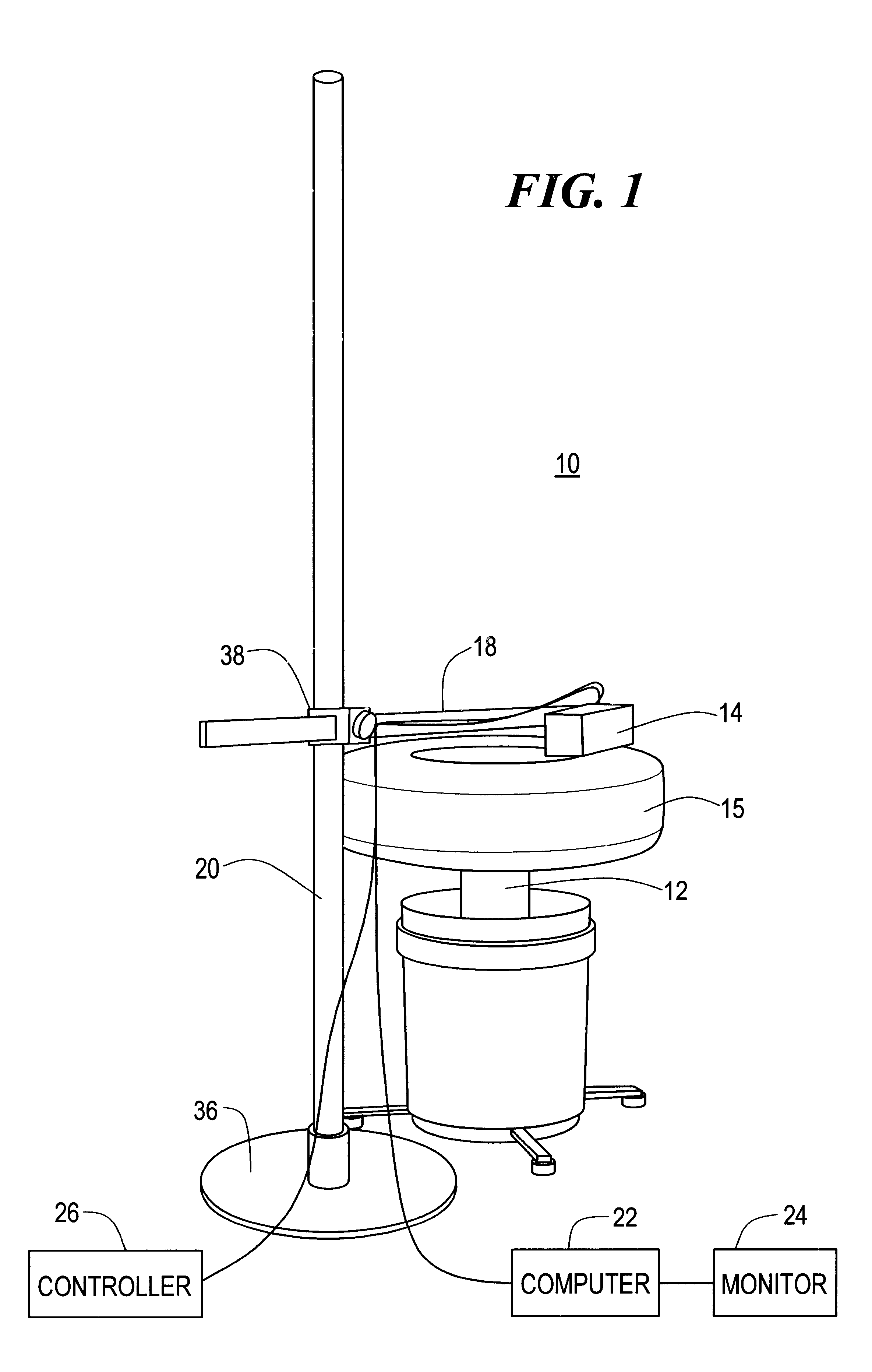
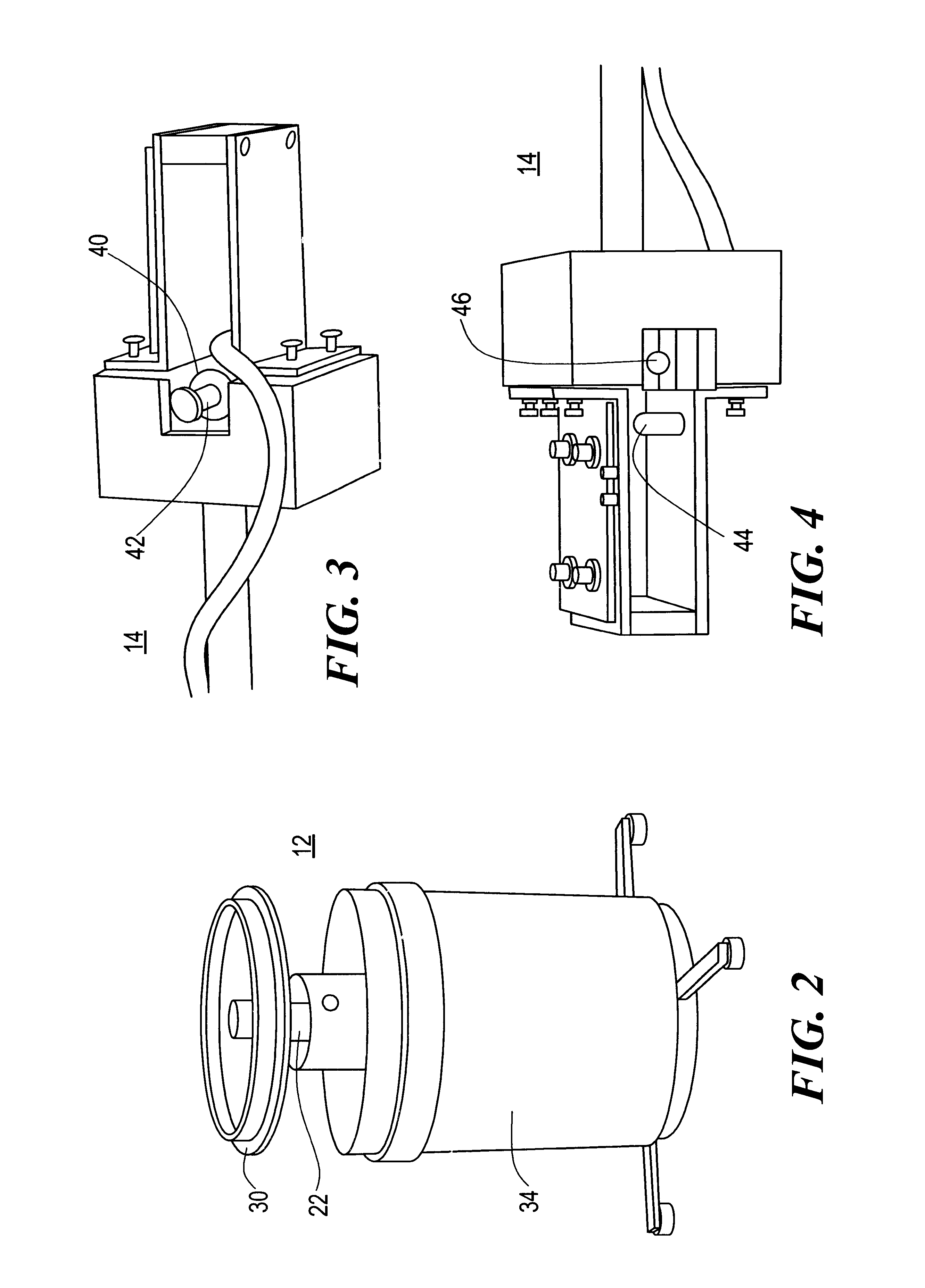
FIG. 2 is a schematic view of the support structure for receiving a tire of the tire defect detection system shown in FIG. 1;

FIG. 3 is a top view of the actuator / microphone fixture of the tire defect detection system shown in FIG. 1;

FIG. 4 is a bottom view of the actuator / microphone fixture shown in FIG. 3;

FIG. 5 is a block diagram of the controller of the tire defect detection system shown in FIG. 1;

FIG. 6 is a schematic view depicting the method of detecting defects in accordance with the subject invention;

FIG. 7 is a front view of the monitor of the tire defect detection system shown in FIG. displaying an image of the tire wall and defects;

FIG. 8 is a graph of the FFT of the sound wave analyzed in accordance with the subject invention;

FIG...


PUM


Abstract

A tire defect detection system including a support structure for receiving a tire; an actuator disposed proximate the tire for impacting the tire; a microphone disposed proximate the actuator for receiving a sound wave generated when the actuator impacts the tire; and a computer responsive to the microphone, the computer programmed to calculate a number of discriminator quantities from the resulting sound wave and to compare the calculated discriminator quantities with stored discriminator quantities indicative of a defect to determine whether a defect is present in the tire.

Description

This invention relates to a system and method for detecting and locating defects such as delaminations and cuts in various types of tires.BACKGROUND OF INVENTIONOver twenty five million retreaded tires were sold in the United States in 1995 alone. Retreaded tires are used in critical applications such as for military and commercial aircraft and even school buses. As such, when a retreaded tire fails due to a delamination, the result can be disastrous.There have been numerous attempts made to devise inspection devices which can detect defects present in a tire after the tire has been retreaded. Such prior art devices, however, suffer from numerous drawbacks. Holography methods, which map tire defects using optical means are extremely expensive, generally about $500,000 per machine, are extremely sensitive to vibration, and also relatively slow. Shearography is a similar technique less sensitive to vibration, but also very expensive and slow. High voltage tests are less expensive, but...

Claims


Application Information

Patent Timeline
IPC IPC(8): G01N29/46G01N29/48G01M17/02G01N29/04G01N29/44G01N29/12B60C19/00
CPCG01M17/025G01N29/045G01N29/48G01N29/46G01N2291/2692
Inventor HEIRTZLER, FRANK J.HILL, WAYNE S.
Owner FOSTER-MILLER
Why Eureka
Try Eureka