Laser ignition
- Summary
- Abstract
- Description
- Claims
- Application Information
AI Technical Summary
Benefits of technology
Problems solved by technology
Method used
Image
Examples
fifth embodiment
The excitation light source generally is a laser, but may also be a light emitting diode or a flashlamp. Any of a variety of laser systems may be used as an excitation laser light source. For example, excitation laser light may be generated by a Q-switched, cavity dumped or free running laser. For the invention, an excitation light source which can produce more than one wavelength of light is needed.
Q-switched pulses can be obtained from the excitation laser by either active or passive Q-switching of the laser. Excitation lasers which are active or passive Q-switched can be used for all four embodiments of the invention. Generally presently preferred, particularly for the third, fourth and fifth embodiments of the invention, are active Q-switched solid-state laser systems to reduce timing jitter.
A wavelength tunable, Q-switched Cr:LiSAF laser that can be tuned over a wavelength range from about 800 to about 1000 nanometers is presently preferred. The output of such a laser can be tu...
first embodiment
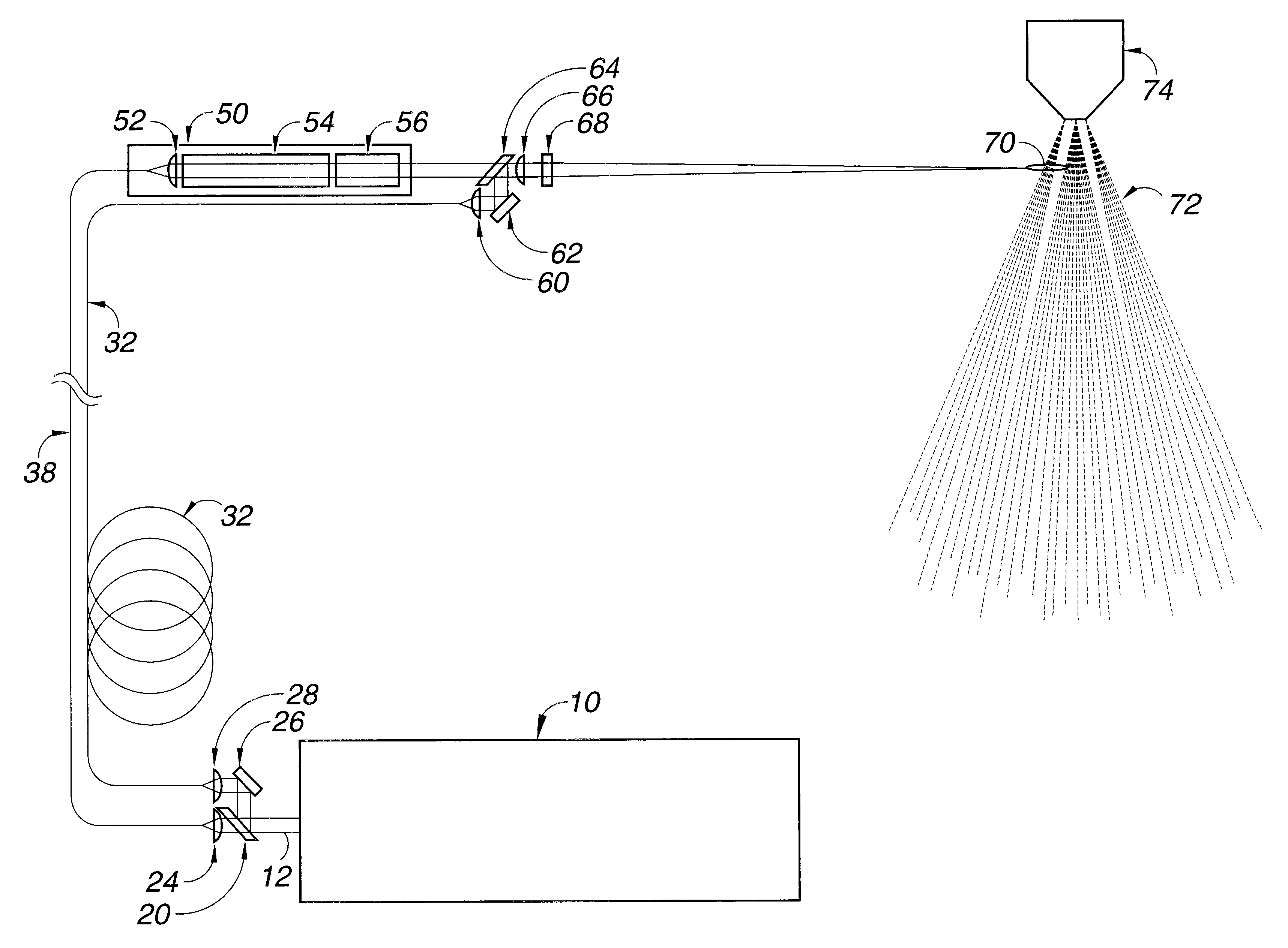
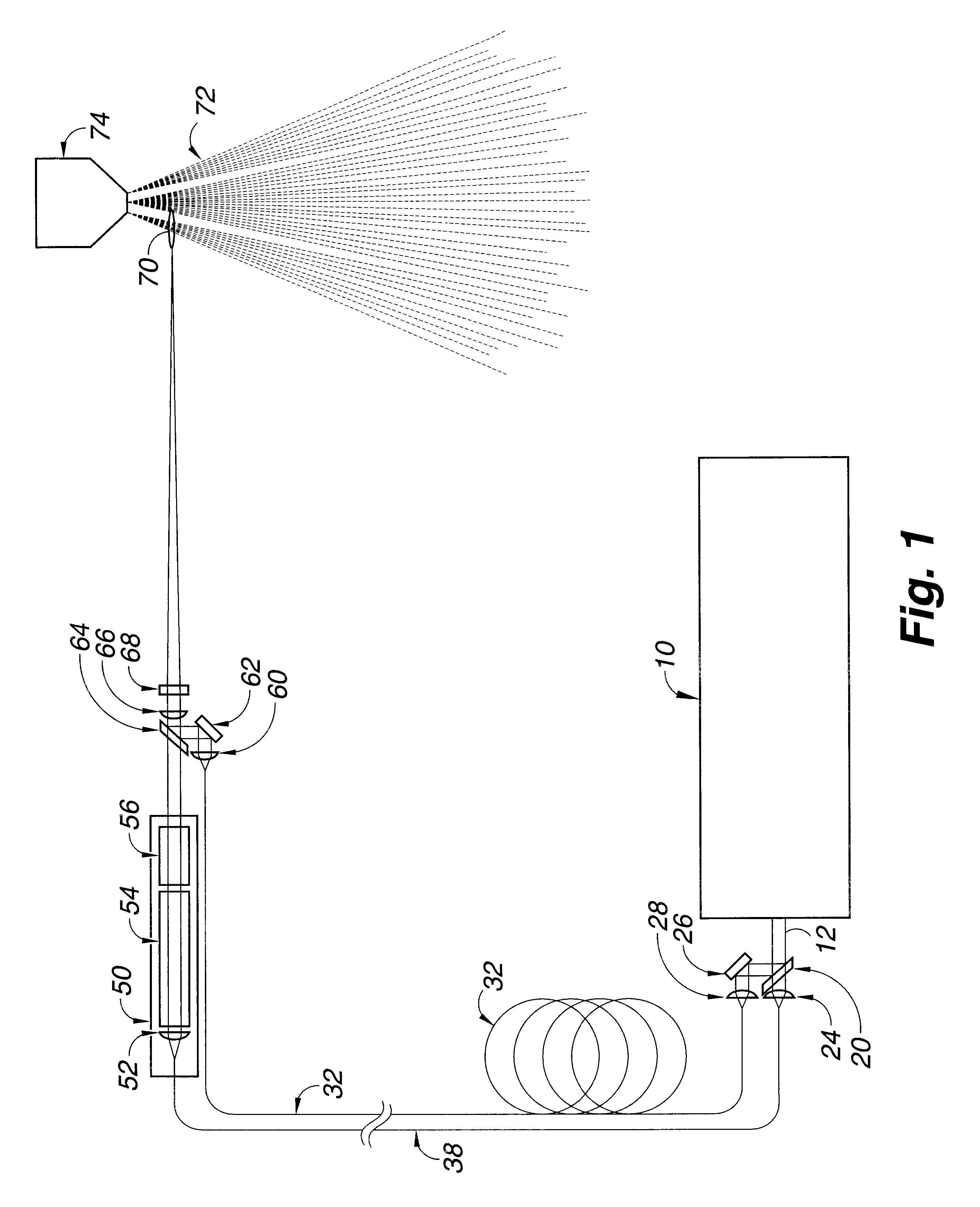
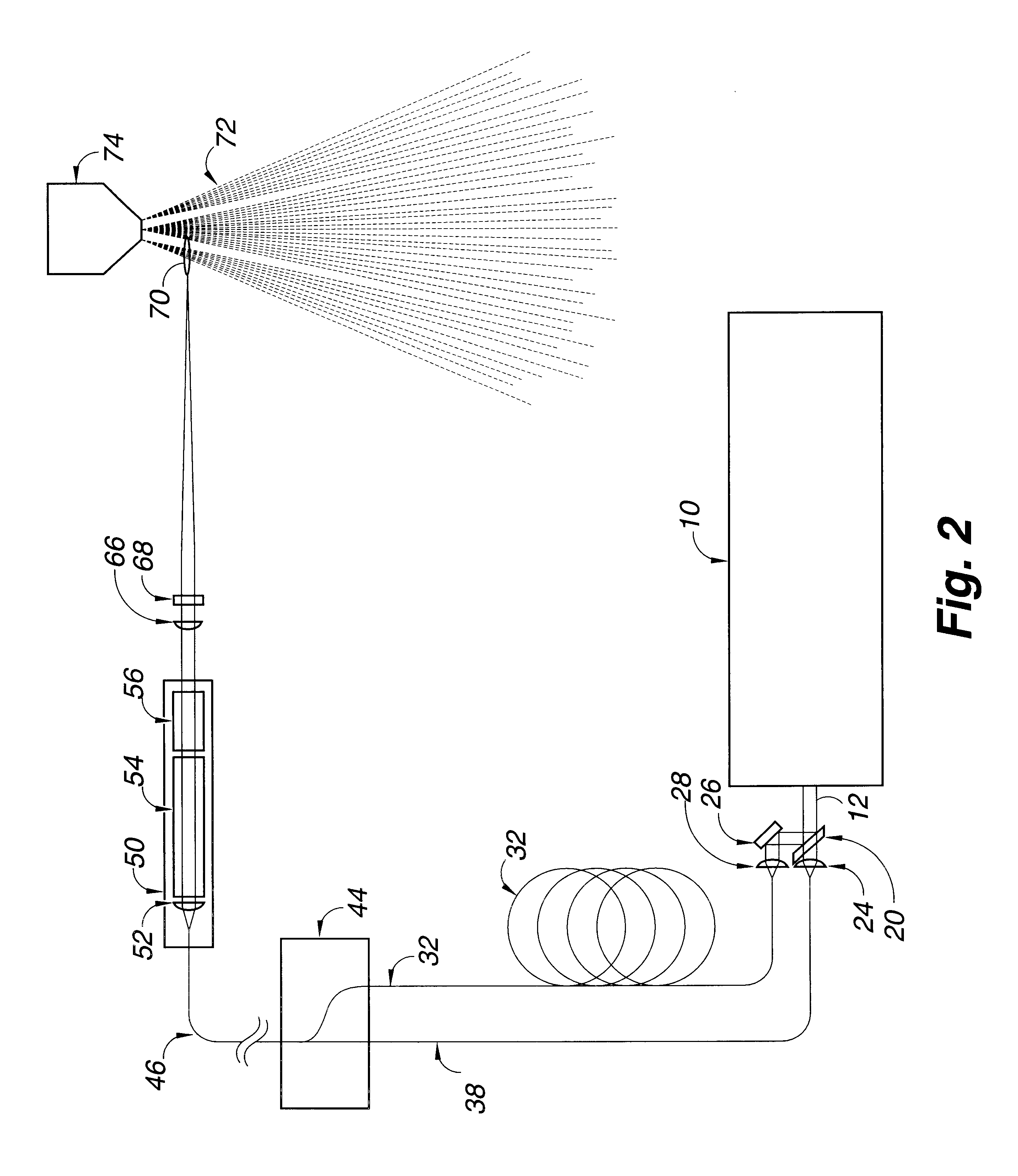
In this first embodiment of the invention, a long duration low peak power pulse of light from the excitation light source is split into two portions, with the first portion being injected into an optical fiber for transportation to the ignitor laser. The two portions into which the light beam from the excitation light source is split can be equal or unequal. When the first portion of the long duration low peak power pulse of light from the excitation light source reaches the ignitor laser, the lasing material is pumped, the Q-switch is activated, and the ignitor laser outputs a short duration high peak power pulse of light, typically from about 10 to about 20 microseconds. The short duration high peak power pulse from the ignitor laser is directed into a beam combiner.
The second portion of the beam from the excitation light source laser is directed through a fiber optic delay line long enough to delay the beam, generally from about 50 to 100 nanoseconds, then through a short focal l...
second embodiment
In this second embodiment of the invention, the time interval between the pulses of light from the excitation light source is created by splitting the beam, delaying a portion of the beam, and then recombining the beam so that pulses of it reach the ignitor laser at intervals of time that are controlled by choice of length of the optic delay line.
As the first portion of the beam from the excitation light source reaches the ignitor laser, the ignitor laser is activated and outputs a short duration high peak power laser light pulse. The short duration high peak power laser light pulse from the ignitor laser is focused into a focal point in an aerosol spray or cloud of combustible fuel, thereby causing breakdown and ionization of the combustible fuel to form a plasma.
Then, before the bleached Q-switch on the ignitor laser has had time to reset (typically about 1 microsecond), the second portion of the long duration low peak power beam from the excitation laser by way of the beam combin...
PUM
 Abstract
Description
Claims
Application Information
 - R&D
- Intellectual Property
- Life Sciences
- Materials
- Tech Scout
- Unparalleled Data Quality
- Higher Quality Content
- 60% Fewer Hallucinations
Browse by: Latest US Patents, China's latest patents, Technical Efficacy Thesaurus, Application Domain, Technology Topic, Popular Technical Reports.
© 2025 PatSnap. All rights reserved.Legal|Privacy policy|Modern Slavery Act Transparency Statement|Sitemap|About US| Contact US: help@patsnap.com


