Laser ignition

a laser excitation source and ignition method technology, applied in the field of fuel ignition, can solve the problems of bulky laser excitation sources, flashing or laser diodes, unreliable laser excitation methods and apparatuses, etc., and achieve the effects of reliable, durable and economical ignition

Inactive Publication Date: 2004-01-13
LOS ALAMOS NATIONAL SECURITY
View PDF17 Cites 68 Cited by
  • Summary
  • Abstract
  • Description
  • Claims
  • Application Information

AI Technical Summary

Benefits of technology

To achieve the foregoing and other objects, and in accordance with the purposes of the present invention, as embodied and broadly described herein, there has been invented a fuel ignition apparatus and method in which an excitation light source is used to activate one or more small ignitor lasers located remotely from the excitation light source and more proximately to one or more fuel combustion zones. Using a separate excitation light source to pump the lasers which ignite the fuel eliminates the need for large, heavy, fragile or complex excitation sources in the harsh operating environments of fuel combustion chambers. Durable, reliable, economical ignition of gaseous or aerosol fuel mixtures can be accomplished with the invention apparatus and method.

Problems solved by technology

These laser ignition methods and apparatuses are generally unreliable except within narrow ranges of fuel parameters such as fuel / oxidizer ratios, fuel droplet size, number density and velocity within a fuel aerosol, and initial fuel and air temperatures.
This requires fragile, bulky laser excitation sources such as flashlamps or laser diodes which are often difficult to fit proximate to fuel combustion zones, particularly in fuel combustion zones in places such as aircraft engines.
Fuel combustion zones are usually harsh, mechanically adverse environments that necessitate sturdy design or frequent replacement of ignition devices subjected to those environments.

Method used


Image

  • Laser ignition
  • Laser ignition
  • Laser ignition

Examples


fifth embodiment

The excitation light source generally is a laser, but may also be a light emitting diode or a flashlamp. Any of a variety of laser systems may be used as an excitation laser light source. For example, excitation laser light may be generated by a Q-switched, cavity dumped or free running laser. For the invention, an excitation light source which can produce more than one wavelength of light is needed.

Q-switched pulses can be obtained from the excitation laser by either active or passive Q-switching of the laser. Excitation lasers which are active or passive Q-switched can be used for all four embodiments of the invention. Generally presently preferred, particularly for the third, fourth and fifth embodiments of the invention, are active Q-switched solid-state laser systems to reduce timing jitter.

A wavelength tunable, Q-switched Cr:LiSAF laser that can be tuned over a wavelength range from about 800 to about 1000 nanometers is presently preferred. The output of such a laser can be tu...

first embodiment

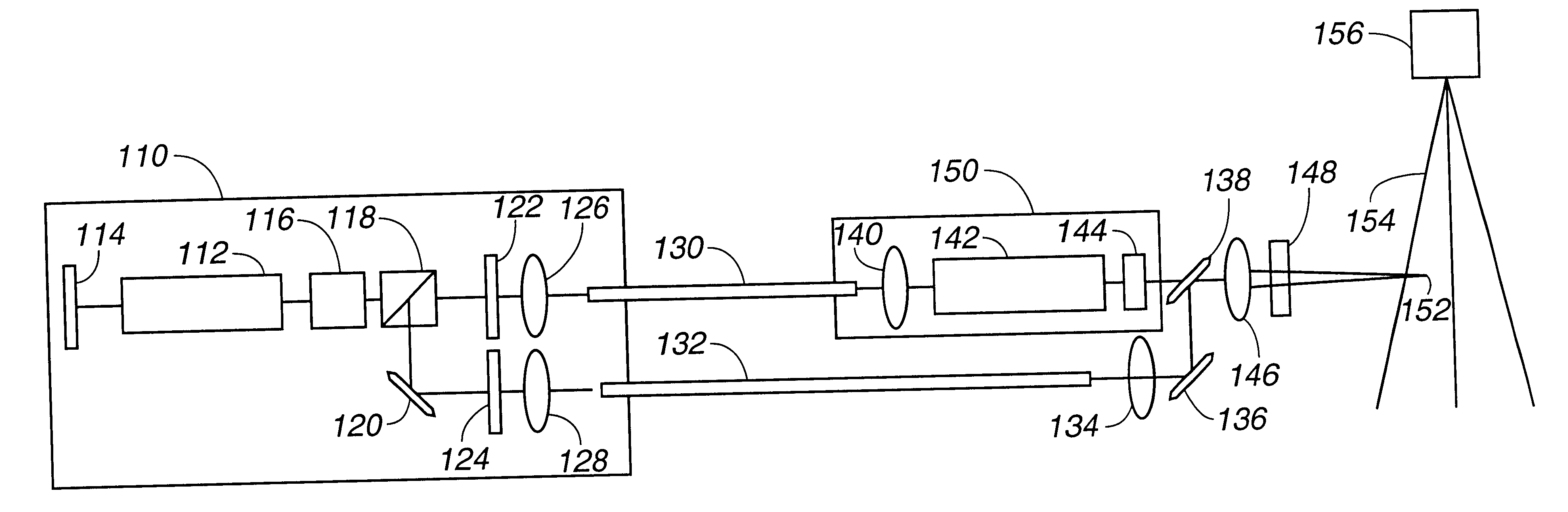
In this first embodiment of the invention, a long duration low peak power pulse of light from the excitation light source is split into two portions, with the first portion being injected into an optical fiber for transportion to the ignitor laser. The two portions into which the light beam from the excitation light source is split can be equal or unequal. When the first portion of the long duration low peak power pulse of light from the excitation light source reaches the ignitor laser, the lasing material is pumped, the Q-switch is activated, and the ignitor laser outputs a short duration high peak power pulse of light, typically from about 10 to about 20 microseconds. The short duration high peak power pulse from the ignitor laser is directed into a beam combiner.

The second portion of the beam from the excitation light source laser is directed through a fiber optic delay line long enough to delay the beam, generally from about 50 to 100 nanoseconds, then through a short focal len...

second embodiment

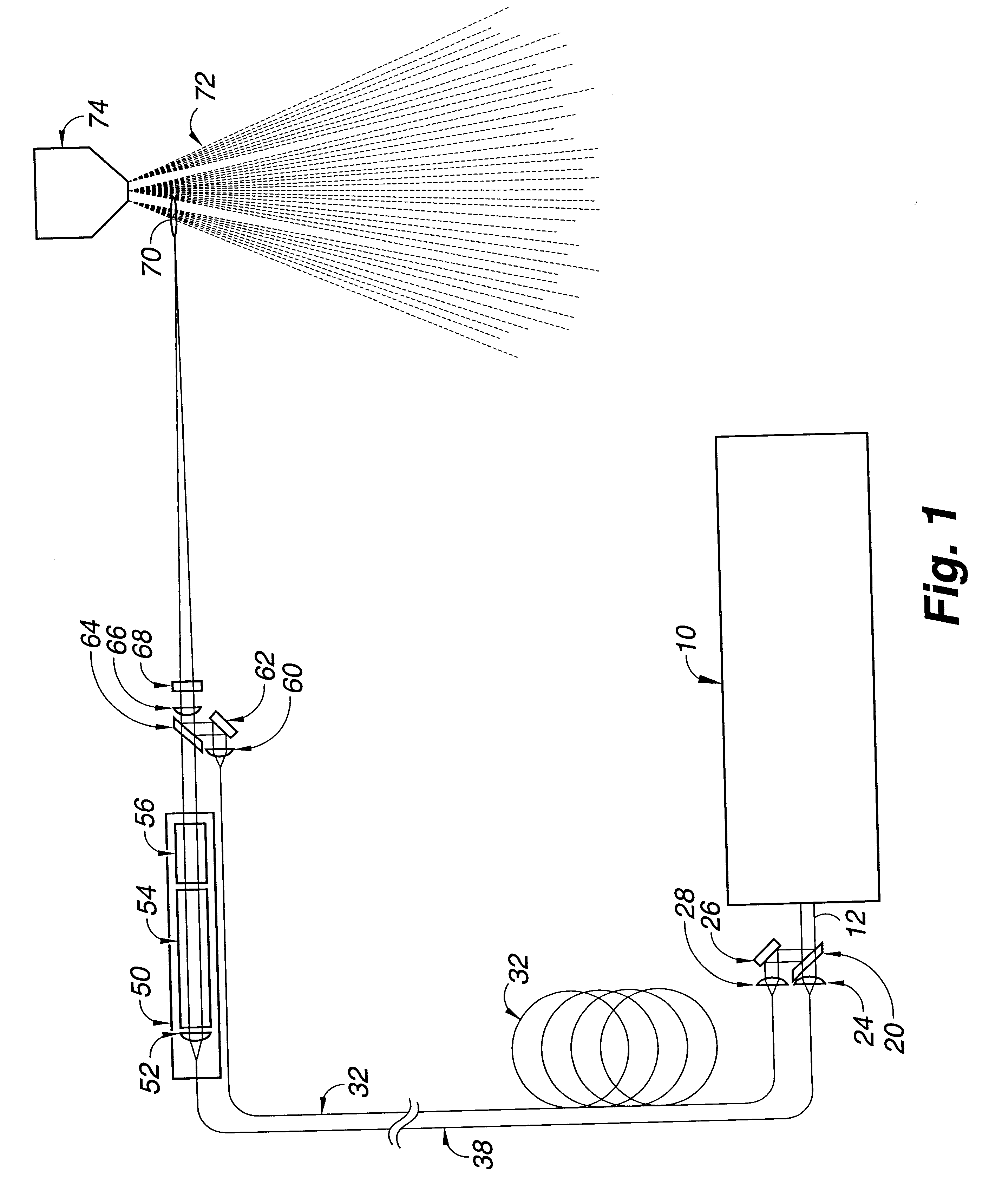
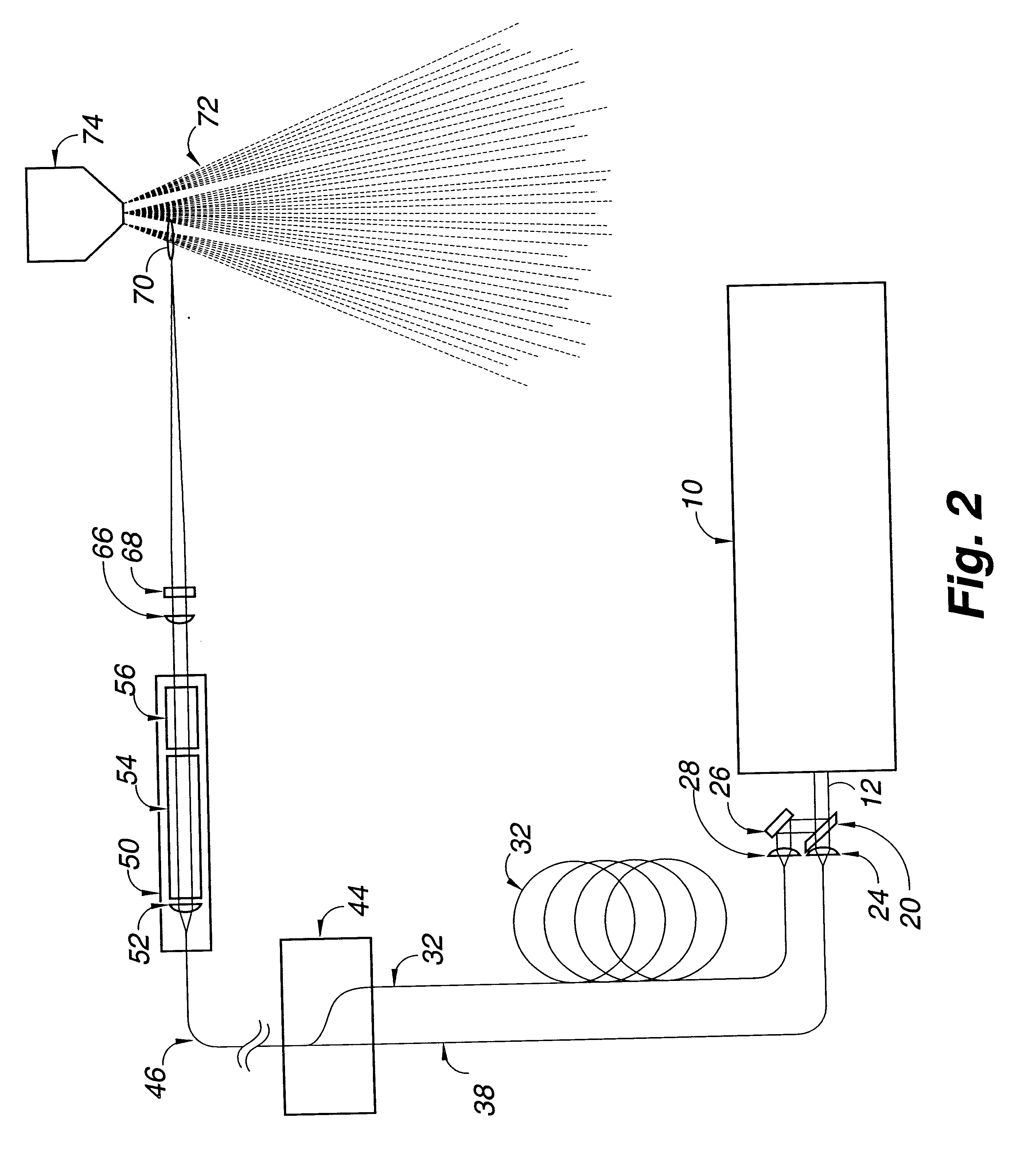
In this second embodiment of the invention, the time interval between the pulses of light from the excitation light source is created by splitting the beam, delaying a portion of the beam, and then recombining the beam so that pulses of it reach the ignitor laser at intervals of time that are controlled by choice of length of the optic delay line.

As the first portion of the beam from the excitation light source reaches the ignitor is laser, the ignitor laser is activated and outputs a short duration high peak power laser light pulse. The short duration high peak power laser light pulse from the ignitor laser is focused into a focal point in an aerosol spray or cloud of combustible fuel, thereby causing breakdown and ionization of the combustible fuel to form a plasma.

Then, before the bleached Q-switch on the ignitor laser has had time to reset (typically about 1 microsecond), the second portion of the long duration low peak power beam from the excitation laser by way of the beam com...


PUM


Abstract

Sequenced pulses of light from an excitation laser with at least two resonator cavities with separate output couplers are directed through a light modulator and a first polarzing analyzer. A portion of the light not rejected by the first polarizing analyzer is transported through a first optical fiber into a first ignitor laser rod in an ignitor laser. Another portion of the light is rejected by the first polarizing analyzer and directed through a halfwave plate into a second polarization analyzer. A first portion of the output of the second polarization analyzer passes through the second polarization analyzer to a second, oscillator, laser rod in the ignitor laser. A second portion of the output of the second polarization analyzer is redirected by the second polarization analyzer to a second optical fiber which delays the beam before the beam is combined with output of the first ignitor laser rod. Output of the second laser rod in the ignitor laser is directed into the first ignitor laser rod which was energized by light passing through the first polarizing analyzer. Combined output of the first ignitor laser rod and output of the second optical fiber is focused into a combustible fuel where the first short duration, high peak power pulse from the ignitor laser ignites the fuel and the second long duration, low peak power pulse directly from the excitation laser sustains the combustion.

Description

This invention relates to a method and apparatus for laser ignition.Laser light has been used to initiate the ignition of fuel / oxidizer mixtures by use of laser-spark, air-breakdown ignition methods in which a single, high peak power laser light pulse from a Q-switched laser is used to initiate fuel ignition by generating high temperatures and an ionization plasma. These laser ignition methods and apparatuses are generally unreliable except within narrow ranges of fuel parameters such as fuel / oxidizer ratios, fuel droplet size, number density and velocity within a fuel aerosol, and initial fuel and air temperatures.After initial ignition, sustaining ignition of fuel / oxidizer mixtures is typically accomplished by use of a laser light pulse from a Q-switched laser with a pulse width and pulse energy which will provide the peak power density required to initiate plasma formation and to satisfy concurrently the need for time-averaged power for sustaining the ignition. This requires frag...

Claims


Application Information

Patent Timeline
Patent Type & Authority Patents(United States)
IPC IPC(8): F02P23/00F02P23/04
CPCF02P23/04H01S3/0602H01S3/094038H01S3/094053H01S3/094061H01S3/2383Y10S123/09
Inventor EARLY, JAMES W.LESTER, CHARLES S.
Owner LOS ALAMOS NATIONAL SECURITY
Why Eureka
Try Eureka