Magnetoelastic sensing apparatus and method for remote pressure query of an environment

Inactive Publication Date: 2002-05-28
UNIV OF KENTUCKY RES FOUND
View PDF24 Cites 133 Cited by
  • Summary
  • Abstract
  • Description
  • Claims
  • Application Information

AI Technical Summary

Problems solved by technology

No currently-available instrument or gage takes advantage of the magneto-elastic emission properties of magnetostrictive materials to obtain a pressure measurement.
Without reasonable, cost-effective solutions at hand for reliably monitoring pressure environments that are difficult

Method used


Image

  • Magnetoelastic sensing apparatus and method for remote pressure query of an environment
  • Magnetoelastic sensing apparatus and method for remote pressure query of an environment
  • Magnetoelastic sensing apparatus and method for remote pressure query of an environment

Examples


Embodiment Construction

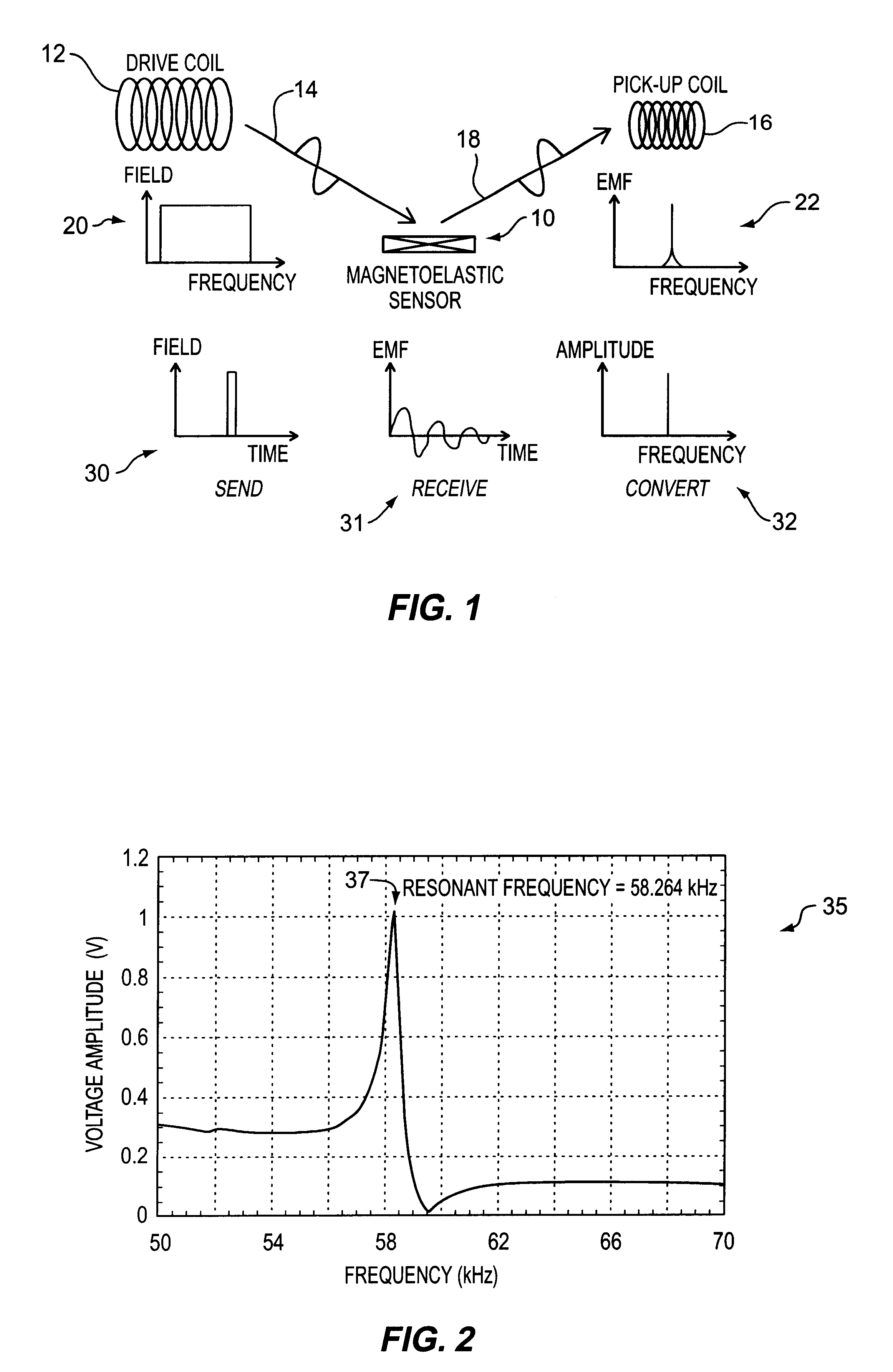
FIG. 1 schematically illustrates a sensor 10 having at least one magnetostrictive element, positioned such that a time-varying electromagnetic (EM) field 14 produced by a drive coil 12 can cause sensor 10 to emit energy 18, here, shown as an EM wave. Shown graphically at 20, an AC magnetic wave generated to sweep over a range of frequencies will cause sensor 10 to emit with a peak at its characteristic frequency (shown graphically at 22). Likewise, as shown graphically in the time-domain at 30, an AC magnetic field pulse causes sensor 10 to emit waves (shown, here, as the transitory time-response curve 31) which can readily be converted into the frequency domain by finding the Fourier transform of the time-response curve. Once performed, the result is as graphed 32 with a spike at the characteristic resonant frequency of sensor 10. For such a case, by way of example, the pulse can be emitted, detected, and converted to the frequency domain for comparison with a pre-correlation for t...


PUM


Abstract

A pressure sensing apparatus for operative arrangement within an environment, having: a sensor comprising a hermetically-sealed receptacle, at least one side of which has an flexible membrane to which a magnetically hard element is attached. Enclosed within the receptacle is a magnetostrictive element that vibrates in response to a time-varying magnetic field. Also included is a receiver to measure a plurality of successive values for magneto-elastic emission intensity of the sensor taken over an operating range of successive interrogation frequencies to identify a resonant frequency value for the sensor. Additional features include: (a) the magnetically hard element may be adhered to an inner or outer side of, or embedded within, the membrane; (b) the magnetostrictive element can include one or more of a variety of different pre-formed, hardened regions; (c) the magneto-elastic emission may be a primarily acoustic or electromagnetic emission; and (d) in the event the time-varying magnetic field is emitted as a single pulse or series of pulses, the receiver unit can detect a transitory time-response of the emission intensity of each pulse (detected after a threshold amplitude value for the transitory time-response is observed). A Fourier transform of the time-response can yield results in the frequency domain. Also, an associated method of sensing pressure of an environment is included that uses a sensor having a magnetostrictive element to identify a magneto-elastic resonant frequency value therefore. Using the magneto-elastic resonant frequency value identified, a value for the pressure of the environment can be identified.

Description

In general, the present invention relates to telemetry using sensing elements remotely located from associated pick-up and processing units for the sensing and monitoring of pressure within an environment. More particularly, the invention relates to a unique remote pressure sensing apparatus that incorporates a magnetostrictive element (whether hermetically-sealed within a receptacle) and associated new method of sensing pressure of a fluid environment whether under vacuum or in a liquid, gas, or plasma state. Any of a number of applications is contemplated hereby, for example: biomedical applications (whether in vivo or in vitro) including medical test samples, food quality / inspection, monitoring of water (groundwater, treated water, or wastewater flowing in natural waterways, canals, or pipes), and monitoring manufacturing waste, etc. The new pressure sensing apparatus and method(s) provide information by utilizing, or listening for, the magneto-elastic emissions of one or more ma...

Claims


Application Information

Patent Timeline
IPC IPC(8): G01L9/16
CPCG01L9/16
Inventor GRIMES, CRAIG A.STOYANOV, PLAMEN G.KOUZOUDIS, DIMITRIS
Owner UNIV OF KENTUCKY RES FOUND
Why Eureka
Try Eureka