Testing method for non-destructive testing of a welded connector, a testing device and an ultrasonic welding apparatus having such a device

a testing device and connector technology, applied in the direction of electrically conductive connections, material strength using steady bending forces, conductors, etc., can solve the problems of affecting the installation of wiring harnesses with faulty or no go (defective) welds, prohibitively expensive and time-consuming, and the whole damaged wiring harness would need to be removed as a whol

Inactive Publication Date: 2002-05-28
SCHUNK ULTRASCHALLTECHN
View PDF15 Cites 26 Cited by
  • Summary
  • Abstract
  • Description
  • Claims
  • Application Information

AI Technical Summary

Problems solved by technology

If inspection were to find a weld to be insufficient or unsatisfactory, i.e. failing to produce a satisfactory electrical connection or lacking in mechanical (bonding) strength when the wiring harness has already been installed, the entire damaged wiring harness would need removing as a whole and to be replaced new.
This is prohibitively costly and time-consuming.
Accordingly, it is especially in just-in-time production in automotive engineering not permitting any delay, that it is unacceptable for wiring har

Method used


Image

  • Testing method for non-destructive testing of a welded connector, a testing device and an ultrasonic welding apparatus having such a device
  • Testing method for non-destructive testing of a welded connector, a testing device and an ultrasonic welding apparatus having such a device
  • Testing method for non-destructive testing of a welded connector, a testing device and an ultrasonic welding apparatus having such a device

Examples


Embodiment Construction

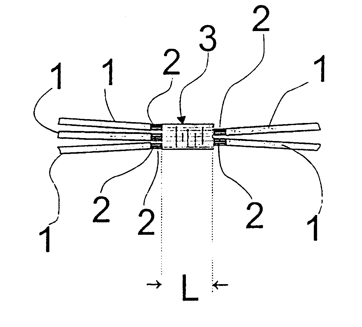
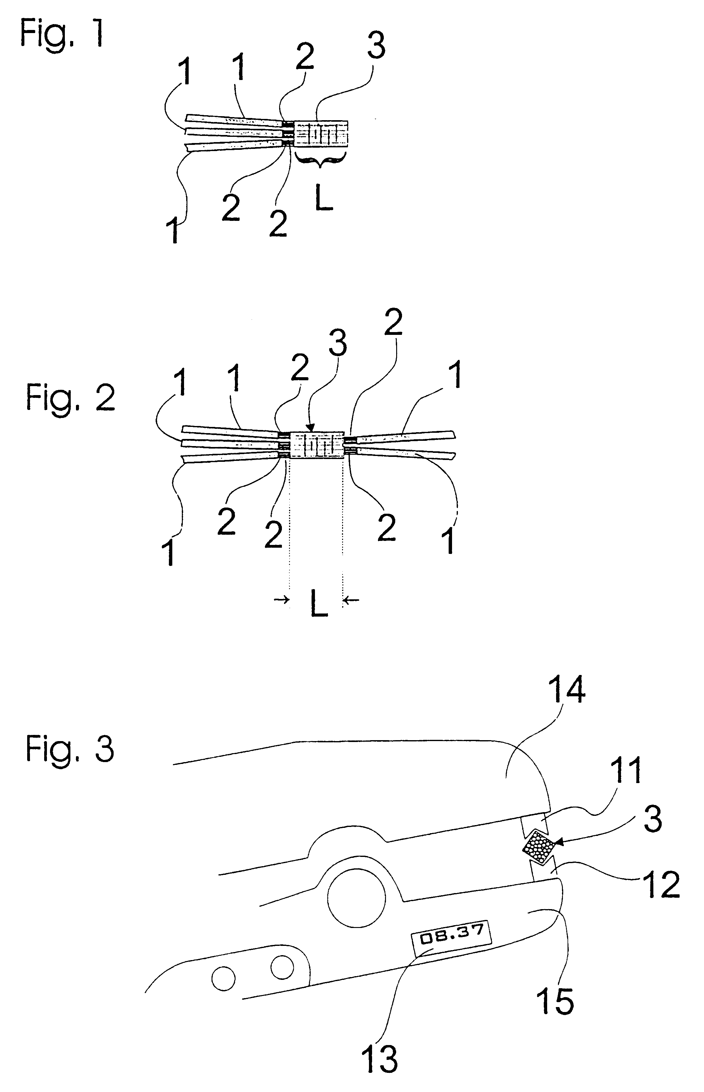
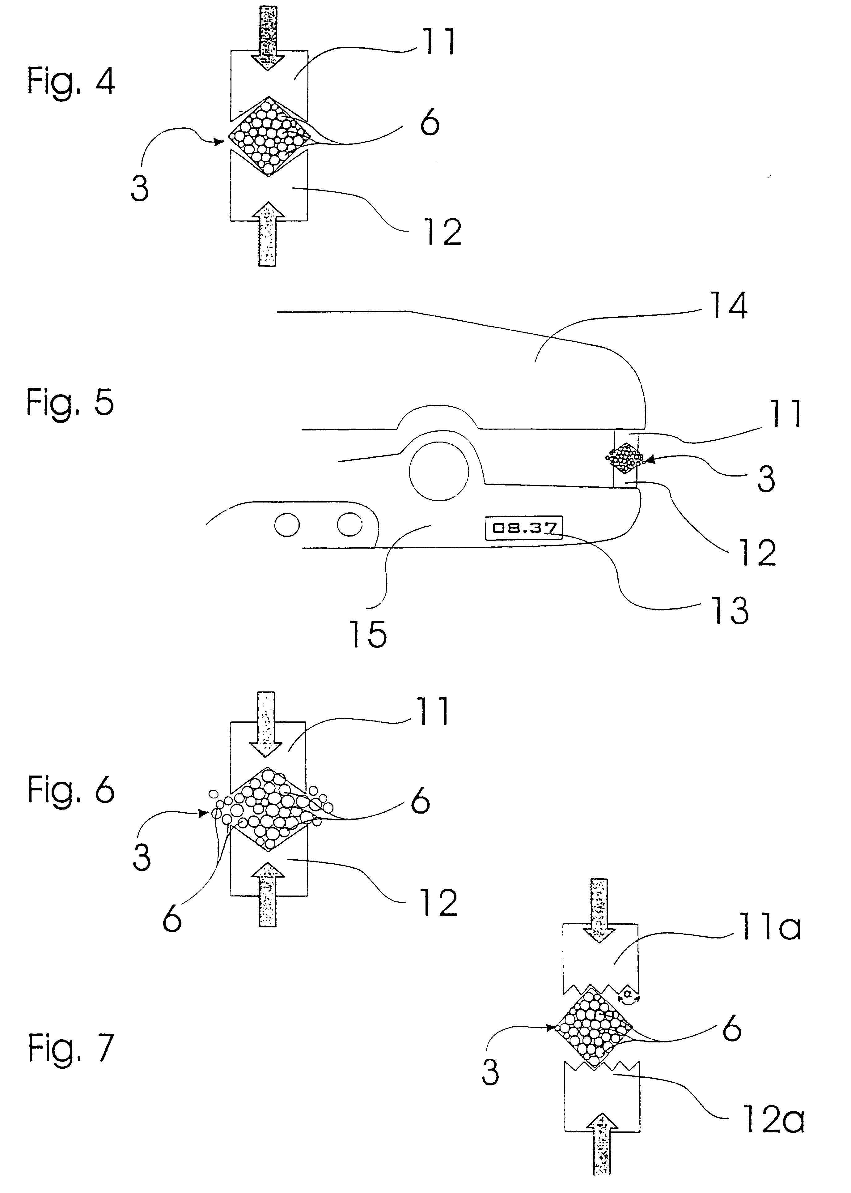
The basic configuration of a weld 3 to be tested by a test method in accordance with the invention for a GO weld is evident more particularly from the FIGS. 1, 2 and 12. In principle, a weld 3 to be tested comprises a plurality of stripped strands 2 of electrical conductors 1. Each strand 2 of an electrical conductor 1 is made up of a plurality of single wires 6 as evident, for example, from the cross-section show in FIG. 4. Over the length L the individual strands 2 of the electrical conductors 1 or, more particularly, the single wires 6 of the plurality of strands 2 have been joined together with an ultrasonic welding juxtaposed in parallel. This means that the individual strands 2 or single wires 6 "bond" to each other at the surface due to a combination of vibration frequency and mechanical pressure. This results in a good electrical contact. It is usual that rectangular or square cross-sections are formed in ultrasonic welding. However, of course, also round, oval, elliptical o...


PUM

PropertyMeasurementUnit
Fractionaaaaaaaaaa
Forceaaaaaaaaaa
Angleaaaaaaaaaa

Abstract

In testing a method for non-destructive testing of a welded assembly which includes a plurality of strands of electrical conductors which are joined together into a bundle by ultrasonic welding, a defined testing force is introduced into two or more shell surface segments of the welded assembly in directions oriented substantially towards each other or substantially to a comon intersection. For carrying out the testing method, a testing device and a welding machine which constitute such a testing device are provided.

Description

The invention relates to a non-destructive method of testing a weld comprising a plurality of strands of electrical conductors joined together into a bundle by ultrasonic welding. Furthermore the invention relates to a testing apparatus for implementing the cited test method and to an ultrasonic welding machine having such an apparatus."Weld" in this context covers any welded connection comprising, more particularly, the following properties. Firstly, two or more stripped strands are joined together by an ultrasonic welding method. It is understood that a strand of an electrical conductor or cable comprises a plurality of single wires. The single wires are designed to conduct an electrical current and are normally made of copper or some other material as generally appreciated in the field concerned. Ultrasonic welding is characterized by each of the single wires to be joined together being heated up by vibration, disrupting the surfaces of the single wires, smoothing out surface irr...

Claims


Application Information

Patent Timeline
IPC IPC(8): B23K20/10B23K31/12G01N19/04G01N3/00G01N19/00H01R43/02H01R4/02
CPCB23K20/10B23K31/12H01R43/0207G01N19/04G01N3/00B23K2201/38G01N2203/0296H01R4/021B23K2101/38
Inventor EDER, ERICHREITHMAIER, JOSEF
Owner SCHUNK ULTRASCHALLTECHN
Why Eureka
Try Eureka